

Views: 0 Author: Site Editor Publish Time: 2026-09-23 Origin: Site


Industrial facilities and commercial plants face heavy utility penalties and constrained grid capacity due to unmanaged reactive power. Poor power factor directly causes premature equipment degradation and excessive energy waste across the entire electrical network. Procuring the wrong compensation equipment leads to critical electrical failures. Under-sizing your equipment results in continued utility fines and unresolved capacity limits. Over-sizing or ignoring harmonic distortion causes severe voltage surges, dangerous resonance, and catastrophic equipment damage. Moving from a reactive power problem to a finalized purchase order requires strict technical evaluation. This guide outlines the exact electrical parameters, environmental constraints, and vendor vetting criteria required to specify and procure the correct low voltage capacitor compensation cabinet for your facility.
Accurate Sizing is Non-Negotiable: Precise kVAr rating calculations based on historical load data and future expansion plans are required to achieve a target power factor (typically >0.95) without over-compensating.
Harmonic Mitigation is Critical: Facilities with non-linear loads (VFDs, LEDs) must assess Total Harmonic Distortion (THD) prior to ordering to determine if detuned reactors are necessary to prevent resonance.
Component Quality Dictates Lifespan: The reliability of a power factor correction cabinet for factory environments depends heavily on the dielectric materials, switching mechanisms (contactors vs. thyristors), and intelligent controllers used.
Vendor Accountability Matters: Selecting a reliable capacitor compensation cabinet manufacturer requires verifying type-test certifications (e.g., IEC standards), component sourcing transparency, and post-installation support capabilities.
Establishing baseline metrics is the first step toward a successful installation. You must define the required power factor improvement clearly. Most industrial grids target a power factor between 0.95 and 0.98. Achieving this eliminates utility penalties and improves overall grid stability. Generic specifications fail because they ignore the unique load profile of your specific facility. Off-the-shelf units rarely align perfectly with complex industrial power demands, leading to mismatched step resolutions and inadequate harmonic protection.
Proper compensation directly enhances your existing transformer capacity. Reactive power consumes valuable space within your electrical infrastructure. When you neutralize this reactive power locally, you free up active power capacity. For example, a 1000 kVA transformer operating at a 0.7 power factor can only deliver 700 kW of useful work. By correcting the power factor to 0.95, that same transformer can deliver 950 kW. This allows for facility expansion and additional load integration without upgrading the main electrical infrastructure.
Beyond avoiding penalties, correct compensation actively lowers overall electricity expenses. Unmanaged reactive power increases the current flowing through your cables and transformers. This elevated current causes higher I²R (copper) losses, which manifest as wasted heat. By installing the right equipment, you reduce these thermal losses. Your entire electrical network operates more efficiently, runs cooler, and consumes less raw energy.
Ordering generic units without a comprehensive site audit introduces massive operational risks. A poorly specified cabinet becomes a liability rather than a grid asset. Common failures associated with generic specifications include:
Transformer Overheating: Undersized units leave transformers under constant thermal stress, degrading winding insulation over time.
Nuisance Tripping: Mismatched capacitor steps cause aggressive voltage fluctuations, tripping main breakers and halting production lines.
Capacitor Degradation: Ignoring facility harmonic profiles leads to the rapid degradation and shortened lifespan of internal capacitor dielectrics.
Resonance Amplification: Installing standard capacitors in a harmonic-rich environment can amplify existing distortion, destroying sensitive electronics downstream.
You must analyze utility bills and peak reactive power demand carefully. Review existing transformer capacity to determine the total required compensation. Calculating the exact kVAr rating requires historical load data captured over several production cycles. Too little compensation will fail to solve the power factor problem, leaving you exposed to utility fines. Conversely, too much compensation causes grid instability. Over-compensation leads to dangerous leading power factors and elevated system voltages that damage lighting and motor circuits.
Evaluate the necessity of fine-step resolution. Industrial loads rarely remain static throughout the day. Smaller capacitor banks prevent over-compensation during low-load periods. If your facility has highly variable loads, you need a cabinet with multiple, smaller switching steps. For instance, a 500 kVAr requirement might be better served by ten 50 kVAr steps rather than five 100 kVAr steps. This granular control ensures the power factor remains stable regardless of production shifts. Coarse step resolution often leads to aggressive hunting, where the controller rapidly switches banks on and off, causing severe mechanical wear.
Matching the cabinet’s rated voltage with the actual grid operating voltage requires accounting for standard fluctuations. During light load conditions, grid voltages naturally rise. Specifying 440V or 480V capacitors for a nominal 400V system ensures long-term longevity. Capacitors operating strictly at their maximum voltage limit degrade rapidly. A higher voltage rating provides a necessary safety buffer against transient spikes and harmonic voltage distortion.
Assess the dielectric materials used within the capacitors. Thermal stability is a strict requirement for industrial environments. Look for capacitors featuring self-healing metallized polypropylene film. When a localized fault occurs, the metallized film vaporizes to isolate the defect, preventing a complete short circuit. Furthermore, verify the presence of overpressure disconnect mechanisms. These mechanical fuses physically break the internal connection if gas pressure reaches critical levels, preventing catastrophic bursting and cabinet fires.
The reactive power controller acts as the brain of the compensation system. Evaluate its ability to continuously monitor grid voltage and current. The controller must accurately calculate real-time reactive power demand and process this data instantly before executing any switching commands. Outdated controllers rely on simple voltage triggers, which often lead to inaccurate compensation. Modern intelligent controllers analyze the entire power triangle, factoring in active power, reactive power, and apparent power to make precise switching decisions.
Ensure the controller features automatic step-switching algorithms. Rapid on/off cycling destroys contactors and capacitors. Intelligent algorithms prevent this erratic behavior by enforcing minimum discharge times before reconnecting a capacitor bank. They also evenly distribute wear across all capacitor banks using circular switching logic. By rotating the switching sequence, the controller ensures no single capacitor bank bears the entire operational load, significantly extending the lifespan of the entire cabinet.
Identify the presence of non-linear loads in your facility's electrical network. Variable Frequency Drives (VFDs), LED lighting arrays, UPS systems, and welding machines generate significant harmonic distortion. Harmonics distort the standard sinusoidal waveform of your electrical supply. Capacitors naturally attract these high-frequency harmonic currents because their impedance decreases as frequency increases. Without protection, capacitors absorb these currents, overheat, and eventually fail prematurely.
Determine exactly when to specify detuned reactors. If your Total Harmonic Distortion (THD) exceeds safe thresholds, reactors are mandatory. These reactors are wired in series with the capacitors to shift the resonance frequency of the network safely below the dominant harmonic orders. This blocks harmonic currents and protects the capacitors from thermal breakdown.
Reactor Tuning Factor | Resonance Frequency (50Hz Grid) | Primary Application | Harmonic Protection Level |
|---|---|---|---|
0% (Standard) | N/A | Clean grids with linear loads (motors, heaters) | None. Vulnerable to all harmonics. |
7% | 189 Hz | Facilities with VFDs and standard non-linear loads | Blocks 5th harmonic and above. |
14% | 134 Hz | Heavy industrial sites with high 3rd harmonic distortion | Blocks 3rd harmonic and above. |
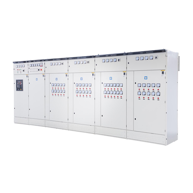
Compare off-the-shelf models against engineered-to-order solutions. Standard models work well for facilities with highly predictable, linear load profiles and ample electrical room space. However, you must evaluate spatial constraints, cable entry requirements, and unique integration needs. Standard cabinets have fixed dimensions that may not fit into crowded electrical rooms. They also feature pre-set step resolutions that might not align with your specific load fluctuations.
Discuss scenarios where a custom capacitor compensation cabinet is absolutely mandatory. Highly corrosive environments, such as wastewater treatment plants or chemical processing facilities, require specialized stainless steel enclosures and conformal coating on circuit boards. Non-standard dimensions dictate custom metalwork to fit low ceilings or narrow aisles. Specialized harmonic profiles demand tailored reactor sizing and unique tuning frequencies. A custom approach ensures the equipment survives the specific environmental and electrical hazards of your facility.
The GGJ series architecture represents a benchmark in modern power distribution networks. It provides a highly structured and reliable framework for reactive power management. A GGJ low voltage compensation cabinet integrates seamlessly with standard low-voltage switchgear. Its widespread application stems from its adaptable design, allowing it to serve both commercial buildings and heavy industrial plants effectively while maintaining strict safety standards.
Verify key features in authentic GGJ configurations. Modularity is a primary advantage. You can easily swap out individual capacitor modules for maintenance without shutting down the entire cabinet. Verify the inclusion of intelligent reactive power controllers and inspect the robust busbar designs. High-quality copper busbars ensure safe current carrying capacity and reduce internal thermal losses during peak operation. Aluminum busbars, while cheaper, often lead to connection degradation and increased heat generation over time.
Evaluate traditional electromechanical contactors for stable, slow-changing loads. Contactors are cost-effective and widely understood by maintenance teams. They work perfectly for general factory lighting or continuously running motors. However, they are prone to mechanical wear over time. Contactors also generate significant inrush currents when switching capacitors online. This transient stress degrades the capacitor dielectric over thousands of cycles, eventually requiring replacement.
Evaluate thyristor-based (static) switching for rapidly fluctuating loads. Spot welding machines, overhead cranes, and injection molding machines demand instant reactive power. Thyristors provide zero-crossing switching capabilities. They engage the capacitor exactly when the voltage crosses zero, eliminating inrush currents entirely. Thyristors offer transient-free operation and unlimited switching cycles without mechanical degradation, making them mandatory for dynamic industrial environments.
Feature | Electromechanical Contactors | Solid-State Thyristors |
|---|---|---|
Switching Speed | Slow (Seconds to Minutes) | Instantaneous (Milliseconds) |
Inrush Current | High (Requires damping resistors) | None (Zero-crossing switching) |
Mechanical Wear | High (Moving parts degrade) | None (Solid-state components) |
Ideal Application | Stable, continuous loads | Rapidly fluctuating loads (Cranes, Welders) |
Maintenance Frequency | High (Contact inspection required) | Low (Requires clean heat sinks) |
Verify strict adherence to international electrical standards. Compliance with IEC 61439-1/2 and IEC 61921 is non-negotiable for industrial safety. You must also ensure the equipment meets all local electrical codes and grid connection requirements. Uncertified equipment poses severe fire risks and may void your facility's insurance policies in the event of a catastrophic failure. Always request physical copies of the certification documents before proceeding with procurement.
Demand proof of type-tested assemblies (TTA). A reputable manufacturer will provide documentation showing the design has been rigorously validated by an independent testing laboratory. Type testing ensures the cabinet possesses the required short-circuit withstand strength to survive grid faults. It also confirms that internal temperature rise limits remain within safe operational boundaries under full load. Do not accept self-certified claims without independent laboratory verification.
Investigate the origin and brand reputation of critical internal components. The overall reliability of the cabinet depends entirely on its weakest part. Ask for a detailed bill of materials. Identify the brands supplying the capacitors, intelligent controllers, switchgear, and detuned reactors. Premium components ensure a longer operational lifespan and fewer unexpected maintenance shutdowns. Substandard capacitors will bulge and leak within the first year of heavy operation.
A reliable capacitor compensation cabinet supplier maintains complete transparency regarding their supply chain. They will openly discuss why they selected specific contactors or thyristors for your application. Avoid suppliers who substitute specified premium components with cheaper, unverified alternatives during the manufacturing process. Component transparency is a direct indicator of the supplier's overall integrity and technical competence.
Evaluate the warranty terms carefully before signing any purchase order. A standard one-year warranty often falls short for heavy industrial equipment. Negotiate for extended coverage on critical components like the capacitors and controllers. Guarantee the availability of spare parts for at least ten years. Obsolete components turn a minor repair into a major system replacement, causing unnecessary downtime and capital expenditure.
Assess the capacitor compensation cabinet manufacturer and their ability to provide technical support SLAs. Do they offer guaranteed response times for troubleshooting? Commissioning assistance is vital for complex setups involving harmonic mitigation. Ensure the manufacturer provides dedicated engineering support during the initial startup phase to tune the controller parameters perfectly to your grid and verify all safety interlocks.
Check ventilation and cooling requirements thoroughly. Capacitors and reactors generate significant heat during normal operation. Heat causes rapid thermal degradation of capacitor dielectrics, cutting their lifespan in half for every 10°C rise above their rated temperature. Ensure the electrical room has adequate ambient cooling. The cabinet itself must feature forced-air ventilation fans. Verify that the air intake and exhaust louvers are positioned to optimize internal airflow across the hottest components.
Verify the required Ingress Protection (IP) rating based on the specific installation environment. An IP20 rating is sufficient for clean, climate-controlled electrical rooms. However, industrial environments demand higher protection. If you are installing the equipment on a dusty factory floor, near moisture, or in areas with conductive airborne particles, an IP54 or IP65 rating is necessary. Incorrect IP ratings lead to dust accumulation, tracking across insulators, and eventual short circuits.
Ensure physical and electrical compatibility with your existing infrastructure. The new equipment must align perfectly with incoming line cabinets and low-voltage distribution boards. Check busbar alignment, cable entry points (top vs. bottom entry), and overall cabinet dimensions. Seamless physical integration reduces installation time and minimizes costly modifications to your existing electrical room layout. Measure door clearances to ensure maintenance personnel can safely access the internal components.
Verify communication protocols for modern facility integration. The low voltage capacitor compensation equipment should not operate in isolation. It must communicate with your facility-wide SCADA or energy management systems. Specify controllers that support industry-standard protocols like Modbus RTU or Modbus TCP. This allows your maintenance team to monitor power factor trends, track harmonic levels, and assess cabinet health remotely in real-time.
Plan for comprehensive baseline commissioning tests. Never energize a new cabinet without verifying all connections. Measure branch currents to ensure balanced load distribution across all phases. Verify that the intelligent controller parameters match the actual site conditions, including the C/k ratio and switching delay times. Check the polarity of the Current Transformers (CTs). Incorrect CT installation—such as placing them on the wrong side of the load or reversing the polarity—is the most common cause of controller malfunction during initial startup.
Establish a realistic and strict maintenance schedule. Routine inspections prevent catastrophic failures. Follow these basic maintenance steps:
Inspect for visual signs of capacitor bulging or fluid leakage monthly.
Tighten all loose wiring terminals annually, as thermal cycling naturally loosens connections over time.
Check the operation of ventilation fans and clean the air filters quarterly to maintain proper airflow.
Verify contactor health by inspecting for pitted or blackened contacts during scheduled shutdowns.
Perform thermal imaging scans on busbar connections to identify high-resistance hot spots before they cause a fire.
Deploy a portable power quality analyzer at your main incoming feed for 72 hours to capture an accurate baseline of your active power, reactive power, and harmonic distortion profiles.
Calculate your exact kVAr requirements and determine the necessary step resolution based on your lowest and highest production shifts to prevent over-compensation.
Audit your electrical room to define the maximum allowable cabinet dimensions, required cable entry points, and necessary Ingress Protection (IP) rating for the environment.
Request detailed bills of materials from shortlisted vendors to verify the origin of capacitors, reactors, and switching components before signing any purchase orders.
A: Its primary function is to supply reactive power to the electrical grid. This improves the power factor, reduces I²R thermal losses in cables, frees up transformer capacity, and eliminates utility penalties associated with poor power quality. By neutralizing reactive power locally, the main electrical infrastructure operates more efficiently and runs cooler.
A: You must analyze your utility bills, measure peak active power (kW), and determine your current and target power factor. Using these metrics, electrical engineers calculate the exact kVAr required to bridge the gap. You should also factor in future facility expansions to ensure the cabinet has enough capacity to handle additional loads.
A: Choose a custom model when your facility has severe spatial constraints, highly corrosive environments, or complex harmonic distortion profiles. Standard cabinets have fixed dimensions and generic reactor tuning. Custom units allow for specialized enclosure materials, non-standard dimensions, and specifically tuned reactors designed to handle the exact harmonic frequencies generated by your equipment.
A: A power factor correction cabinet for factory environments often faces high harmonic distortion from VFDs and heavy machinery. Detuned reactors block these harmful high-frequency currents. Without them, capacitors absorb the harmonics, overheat, and fail prematurely. Reactors shift the resonance frequency of the network safely below dominant harmonic orders, protecting the equipment.
A: The controller continuously monitors the grid's voltage and current via connected transformers. It calculates the phase angle difference between them to determine real-time reactive power demand. Modern controllers analyze the entire power triangle instantly, executing precise switching commands to maintain the target power factor without causing rapid on/off cycling or grid instability.
A: Contactors are mechanical switches suited for stable, slow-changing loads, but they suffer from mechanical wear and generate inrush currents. Thyristors are solid-state devices that provide instantaneous, zero-crossing switching. They engage the capacitor exactly when the voltage crosses zero, eliminating inrush currents entirely. Thyristors are mandatory for rapidly fluctuating loads like welding machines and cranes.
A: Standard maintenance includes visually inspecting capacitors for bulging or fluid leaks. You must tighten all electrical terminals to prevent arcing caused by thermal cycling. Test the cooling fans, clean the ventilation filters, and verify the operational health of the contactors. Finally, check the intelligent controller for any logged error codes or abnormal switching patterns.


