

Views: 0 Author: Site Editor Publish Time: 2026-09-21 Origin: Site


Industrial facilities run on heavy inductive loads. Motors, transformers, and HVAC chillers dominate the electrical demand on the plant floor. These machines require magnetic fields to spin and function, pulling reactive current straight from the utility feed. This unmanaged reactive power chokes your electrical infrastructure. It triggers heavy utility penalties, eats up usable transformer capacity, and burns out switchgear through excessive heat. Grid operators now strictly enforce power factor limits to maintain regional voltage stability. You cannot ignore this operational reality. Fixing it requires logging your facility's load profile to see exactly where and when deploying reactive power compensation makes financial and technical sense for your specific site.
Utility Penalties Drive Initial ROI: Facilities consistently operating below a 0.85–0.95 power factor (depending on local utility regulations) will see the fastest payback periods through penalty elimination.
Capacity Recovery is a Hidden Benefit: Compensating reactive power at the load or distribution level frees up transformer and cable capacity, potentially deferring costly infrastructure upgrades.
Grid Stability and Compliance: Proper compensation enhances the transfer of active power across the distribution network, ensuring compliance with evolving grid codes and transmission provider mandates.
Harmonic Analysis is Non-Negotiable: Installing standard capacitors in a harmonic-rich environment (e.g., plants with heavy VFD usage) risks catastrophic resonance; detuned systems are often required.
Customization Matters: Off-the-shelf solutions frequently fail in complex industrial environments; partnering with a specialized low voltage switchgear manufacturer ensures proper integration and thermal management.
Utility companies measure and bill for both active energy (kWh) and reactive energy (kVARh). Active energy performs the actual mechanical work, like turning a conveyor belt motor. Reactive energy sustains the magnetic fields required by those motors to operate. The ratio of active power to apparent power (kVA) represents your power factor. When a facility draws excessive reactive power, the utility must size its generation plants and transmission lines to handle that extra current, even though it performs no usable work at your site.
To recover these heavy infrastructure costs, utilities enforce strict threshold limits. These limits typically sit between 0.90 and 0.95 depending on your region. If your plant's power factor drops below this threshold, the utility applies demand surcharges or penalty tariffs directly to your monthly invoice. Facility managers should pull the past twelve months of utility bills and look at the line items. Consistent kVARh charges or explicit power factor penalties indicate an immediate need for corrective action. Eliminating these recurring monthly fines provides the primary financial justification for installing new compensation equipment.
Poor power factor manifests physically within a plant's electrical network. High reactive current increases the total current flowing through your cables, busbars, and main switchgear. This excess current generates significant heat due to I²R losses, commonly known in the field as copper losses. Over time, this constant thermal stress degrades cable insulation, hardens wire jackets, and accelerates the aging of critical electrical components.
Operators walking the plant floor may notice several physical symptoms indicating unmanaged reactive power. You might see chronic voltage sags during the startup of large motors, causing lights to dim or sensitive relays to drop out. You might find distribution transformers running dangerously hot even when operating well below their maximum kW rating. Nuisance tripping of circuit breakers is another common symptom, caused by the elevated total current pushing the breaker past its thermal trip curve. Addressing the root cause by compensating reactive power locally reduces the total current drawn from the transformer. This lowers operating temperatures, stabilizes voltage levels, and extends the operational lifespan of your distribution equipment.
Reactive power consumes apparent power (kVA) capacity. Transformers and backup generators are rated in kVA, not kW. If you have a 2000 kVA transformer operating at a poor 0.75 power factor, it can only deliver 1500 kW of useful active power. The remaining capacity is entirely occupied by reactive current. When a plant plans to add new production lines, welding cells, or heavy machinery, this capacity bottleneck becomes a massive roadblock.
Instead of spending heavy capital on a larger transformer and ripping out the main incoming switchgear, facilities can install compensation equipment. Improving the power factor to 0.95 on that same 2000 kVA transformer increases the available active power to 1900 kW. You instantly recover 400 kW of usable capacity. This capacity recovery defers major capital expenditures and allows for facility expansion using the exact same electrical infrastructure you already have in place.
Uncompensated reactive power degrades broader grid voltage stability. When large industrial plants draw massive amounts of reactive current, voltage levels on the utility distribution network drop. This affects neighboring facilities and forces the utility to deploy its own massive compensation equipment at local substations to prop up the voltage.
Regulatory frameworks increasingly require industrial consumers to operate within a standard power factor range. Compliance ensures grid reliability for everyone. Localized compensation enhances the efficient transfer of active power across both your internal plant networks and the external utility distribution grids. Failing to meet these regulatory standards can result in severe financial penalties. In extreme cases during peak summer load events, utilities have the authority to mandate disconnection from the grid if your facility threatens regional voltage stability.
Industrial facilities typically implement low voltage reactive power compensation operating between 400V and 690V. Engineers must decide between centralized and decentralized compensation strategies based on the plant's physical layout and load distribution.
Centralized compensation involves installing large capacitor banks directly at the main low voltage distribution board. This approach is highly cost-effective, easy to maintain, and corrects the power factor seen by the utility meter, instantly killing penalties. However, it does not reduce the reactive current flowing through the plant's internal sub-distribution cables. Decentralized compensation places smaller capacitors directly at individual large motor loads. This maximizes active power delivery throughout the entire internal network and minimizes I²R losses in trailing cables. While decentralized systems require higher initial installation costs and more maintenance points, they offer superior internal capacity recovery.
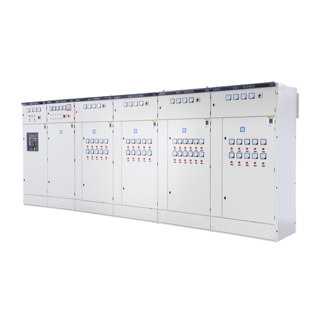
The GGJ capacitor compensation cabinet serves as a standard, reliable solution for centralized power factor correction in heavy industrial settings. These cabinets house multiple capacitor steps, heavy-duty switching devices, and protective HRC fuses within a standardized, rugged metal enclosure.
Designed for modularity, the GGJ cabinet allows maintenance technicians to easily add or replace capacitor modules as facility loads change over the years. The system relies on an automatic power factor controller (APFC) mounted on the front door. The APFC continuously monitors the network's reactive power demand via a current transformer (CT) and intelligently switches capacitor steps in and out of the circuit. This dynamic response makes the cabinet highly suitable for manufacturing environments with fluctuating load profiles, ensuring the power factor remains consistently within the target range without any manual intervention from operators.
Selecting the right control mechanism depends entirely on the nature of your connected loads. Applying the wrong system can introduce severe electrical instability and damage equipment.
System Type | Operational Characteristic | Ideal Application | Primary Risks |
|---|---|---|---|
Fixed Compensation | Capacitors are permanently connected to the load and switch on/off simultaneously with the equipment. | Large, continuously running motors, constant-load transformers, or irrigation pumps. | Over-compensation (leading power factor) if left online when the load is disconnected, causing severe voltage spikes. |
Automatic Contactor Systems | Controller dynamically switches multiple capacitor steps using mechanical contactors based on real-time demand. | Main distribution boards, mixed manufacturing lines, facilities with variable loads. | Requires regular maintenance of contactors due to frequent mechanical switching cycles and inrush wear. |
Thyristor Switched Systems (Static) | Uses solid-state thyristors to switch capacitors in milliseconds without moving parts. | Spot welding lines, large cranes, plastic injection molding machines with rapid load swings. | Higher initial capital cost and requires robust cooling for the solid-state components. |
Specifying an industrial power factor correction cabinet requires a comprehensive power quality audit. Guessing capacitor sizes based solely on utility bills often leads to catastrophic equipment failure. Modern industrial plants utilize non-linear loads extensively. Variable frequency drives (VFDs), arc furnaces, welding equipment, and LED lighting generate harmonic currents that distort the standard 50Hz or 60Hz sine wave.
Capacitors present a low impedance path to high-frequency harmonics. When standard capacitors are installed in a harmonic-rich environment, they absorb these high-frequency currents, leading to rapid overheating, swelling, and premature failure. More critically, the combination of capacitors and the network's transformer inductance can create a resonant circuit. To prevent harmonic resonance, engineers must specify detuned reactors connected in series with the capacitors. Depending on the harmonic spectrum (typically 5th, 7th, or 11th harmonics), tuning frequencies of 7% or 14% are standard requirements to protect the compensation equipment and the broader plant network.
Standard, pre-configured cabinets work well in clean, temperature-controlled commercial environments. However, they frequently fail when exposed to harsh industrial conditions. Heavy airborne dust, corrosive gases, high ambient temperatures, and strict space constraints demand specialized engineering.
A custom reactive power compensation cabinet addresses these specific site challenges. When evaluating your site, look for these specific customization criteria:
Specific footprint dimensions to fit within existing crowded electrical rooms or tight mezzanine spaces.
Advanced harmonic filtering capabilities tailored to the exact THD profile of the plant, utilizing specific reactor tuning.
Specialized ingress protection (IP54 or NEMA 12 ratings) to block conductive dust, moisture, or chemical vapors.
Upgraded busbar bracing to withstand high short-circuit fault currents present in large facilities near the main utility feed.
Top or bottom cable entry configurations to match existing trenching or overhead cable trays.
The internal components dictate the reliability and lifespan of the entire system. Procurement teams must evaluate the technical specifications of the core parts rather than just looking at the overall cabinet price. Cheap components will fail within the first two years of industrial use.
Self-healing metallized film capacitors are mandatory. If a localized dielectric breakdown occurs due to a voltage spike, these capacitors isolate the fault internally, preventing a complete short circuit. Switching devices also require careful selection. Standard motor contactors wear out quickly under high capacitive inrush currents. You must specify heavy-duty capacitor switching contactors equipped with pre-charge resistors to mitigate this wear. For applications requiring rapid load changes, thyristor switches provide transient-free, instantaneous switching without mechanical degradation. Finally, the intelligent controller must offer precise step resolution and comprehensive alarm functions for overvoltage, undercurrent, and harmonic overload.
Vetting a capacitor compensation cabinet supplier requires verifying their adherence to strict international standards, primarily IEC 61439 or local equivalents like UL 845. These standards govern the design, assembly, and testing of low voltage switchgear and controlgear assemblies.
A reliable supplier must conduct rigorous factory acceptance testing (FAT) before shipment. This testing should verify control logic, dielectric strength, and protective circuit continuity. Thermal rise testing is particularly critical. The supplier must prove that the cabinet design effectively dissipates the heat generated by reactors and capacitors under full load conditions. Requesting documentation of these type-tests ensures the equipment will perform safely once energized on the plant floor. Do not accept equipment that has only been visually inspected.
Installing compensation equipment is rarely a standalone project. The new cabinet must integrate seamlessly with the facility's existing electrical architecture. Sourcing the equipment from an established low voltage switchgear manufacturer significantly reduces integration risks.
Experienced manufacturers understand the mechanical tolerances required for seamless busbar connections between the new cabinet and the main distribution board. They also ensure compatibility with plant-wide monitoring systems. The APFC should support standard industrial communication protocols, such as Modbus RTU, Modbus TCP/IP, or Profibus. This allows for direct integration into the facility's SCADA or BMS system, giving operators real-time visibility into power factor metrics. This unified approach simplifies installation, reduces downtime during commissioning, and provides a single point of contact for warranty support and troubleshooting.
Harmonic resonance represents the most severe physical risk when implementing compensation systems. When the natural resonant frequency of the capacitor bank and the supply transformer aligns with a harmonic frequency generated by plant loads (like a large VFD), current and voltage amplify exponentially.
The physical consequences of resonance are immediate and destructive. It causes blown step fuses, ruptured capacitor casings, and severe damage to adjacent switchgear components. Mitigation requires mandatory THD-V (voltage distortion) and THD-I (current distortion) measurements prior to equipment design. If distortion levels exceed safe thresholds, engineers must specify detuned reactor banks to shift the resonant frequency safely below the lowest dominant harmonic, usually the 5th harmonic in industrial plants.
Capacitors are highly sensitive to heat. High ambient temperatures inside industrial plants accelerate the degradation of the dielectric film, drastically reducing the equipment's lifespan. A cabinet operating just 10°C above its rated temperature can cut capacitor life in half.
Mitigation strategies focus on aggressive thermal management. Engineers must specify forced ventilation systems with thermostatically controlled cooling fans mounted on the roof or doors. The cabinet must feature appropriate IP ratings that allow airflow while blocking dust ingress, often utilizing washable filter mats. Once installed, maintenance teams should conduct regular thermal imaging inspections under full load to identify localized hotspots on busbar connections or contactor terminals before they escalate into catastrophic failures.
Capacitors store lethal amounts of electrical energy long after the main power is disconnected. Maintenance personnel face severe shock hazards if proper safety protocols are ignored during routine inspections or repairs.
Mitigation starts at the design phase. Ensure the inclusion of high-quality discharge resistors across the capacitor terminals. These resistors must be rated to bleed the residual voltage down to safe levels (typically below 50V) within one to three minutes of de-energization. Operationally, facilities must establish strict lockout/tagout (LOTO) procedures. Technicians must physically verify the absence of voltage using a calibrated multimeter before touching any internal components, regardless of the presence of discharge resistors. Never assume a capacitor is dead.
Securing capital approval requires a realistic framework for calculating Return on Investment (ROI). The most direct financial metric is the complete elimination of utility power factor penalties. By analyzing a year of utility bills, plant managers can quantify the exact annual cost of these surcharges.
Secondary savings come from reduced I²R losses. Lowering the total current running through the plant's distribution network reduces the energy wasted as heat. While these kWh savings are smaller than penalty avoidance, they contribute to the financial model. In high-penalty utility jurisdictions, the combined savings typically result in a payback period of 12 to 24 months. Once the equipment pays for itself, the eliminated penalties transition directly to bottom-line operational savings year after year.
Beyond the immediate payback period, reactive power compensation delivers substantial long-term value. The most significant financial advantage is deferred capital expenditure (CAPEX). By freeing up kVA capacity on existing transformers, plants can add new machinery without spending heavily on utility service upgrades, new trenching, or new substations.
Operating the electrical network at lower temperatures extends the lifespan of cables, breakers, and transformers, reducing long-term replacement costs. Framing the reduction of system-wide energy losses as a measurable contribution to corporate sustainability goals also strengthens the business case. Improved energy efficiency aligns with broader environmental initiatives, demonstrating responsible resource management alongside strict financial prudence.
Reactive power compensation requires precise engineering based on specific facility load profiles, strict grid compliance requirements, and established power quality baselines. Installing the wrong equipment will exacerbate electrical instability and lead to hardware failure. You must approach this as a critical infrastructure upgrade, not a basic commodity purchase.
Take these actionable next steps to begin the process:
Initiate a week-long power quality logging session at the main incoming feed to capture dynamic load changes and harmonic profiles.
Compile the last twelve months of utility bills to calculate the exact financial impact of current kVARh penalties.
Identify any distribution transformers currently operating above 85% capacity to evaluate potential kVA recovery.
Engage a qualified electrical engineer to interpret the logging data before contacting equipment suppliers.
A: The ideal target is typically between 0.95 and 0.98. While 1.0 (unity) represents perfect efficiency, targeting it is rarely practical. Attempting to maintain 1.0 risks over-compensation during sudden load drops, which pushes the system into a leading power factor and causes damaging voltage spikes across the facility.
A: You need a detuned bank if your facility operates significant non-linear loads like VFDs, LED lighting, or arc furnaces. A power quality audit will measure Total Harmonic Distortion (THD). If THD-V exceeds 3% to 5%, or THD-I is high, detuned reactors are mandatory to prevent harmonic resonance and equipment destruction.
A: A well-maintained cabinet typically lasts 10 to 15 years. However, this lifespan is heavily dependent on the operating environment. High ambient temperatures, excessive harmonic stress, and frequent switching cycles without proper maintenance will rapidly degrade the capacitors and contactors, shortening the equipment's life.
A: It primarily reduces apparent power (kVA) and reactive energy (kVARh). It does not significantly reduce active energy (kWh) consumption. The only marginal kWh savings derived from compensation come from reduced I²R (copper) losses in the cables and transformers due to lower total current flow.
A: A standard capacitor bank uses mechanical contactors to switch steps in and out, which takes seconds and causes wear. An SVC uses thyristors for dynamic, transient-free switching in milliseconds. SVCs are required for highly fluctuating loads, like spot welders or large cranes, where standard contactors would fail rapidly.
A: Regulators mandate that industrial facilities maintain their power factor within specified limits to ensure broader grid stability. Compliance prevents voltage sags on the utility network and enhances the efficient transfer of active power. Failing to meet these regulations triggers financial penalties and threatens grid reliability.


