

Views: 0 Author: Site Editor Publish Time: 2026-06-14 Origin: Site


Selecting the right electrical transformer represents a critical engineering decision for any power distribution network. It goes far beyond simply matching voltage ratings. The choice between solid and liquid insulation dictates facility safety compliance. It also determines extensive civil engineering requirements and dictates long-term operational labor demands. Wrong choices often lead to massive infrastructure headaches. Sometimes, they introduce severe environmental or fire risks into highly populated areas. We constantly see facilities forced into complex, disruptive retrofits simply because they misunderstood the fundamental cooling mechanisms of their equipment.
Our objective is to provide an evidence-based, side-by-side technical evaluation. We break down the structural, environmental, and operational differences between these two primary technologies. You will learn how to accurately shortlist the right asset for your specific load profile, installation environment, and physical constraints. We aim to equip procurement managers and electrical engineering teams with precise data. This comprehensive guide ensures you select the optimal asset to support your facility reliably for decades.
Capacity Limits: Dry-type transformers are generally restricted to <35kV and lower load capacities (typically under 1600kVA), while oil-immersed variants handle ultra-high voltage (up to 1000kV+).
Total Cost of Ownership (TCO): Oil-immersed units have lower upfront costs but demand higher maintenance (DGA testing, fluid replacement) and civil infrastructure (bund walls). Dry types cost more initially but require near-zero maintenance.
Safety & Placement: Dry types utilize self-extinguishing solid insulation, making them mandatory for high-density indoor environments. Oil types require stringent fire and leak mitigation, primarily restricting them to outdoor substations.
Understanding the fundamental engineering differences helps us appreciate how each unit behaves under stress. The primary distinction lies entirely in how they isolate electrical currents and manage internal heat buildup.
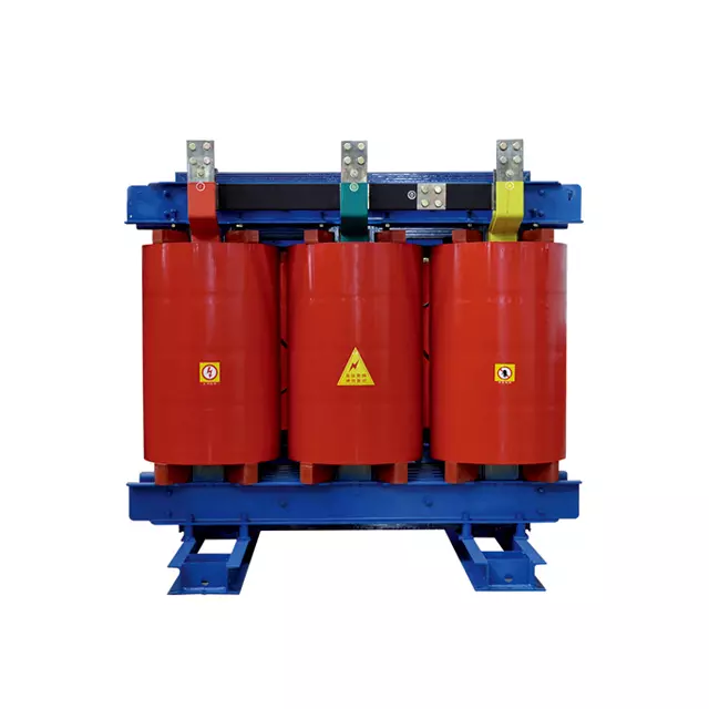
A Dry-type Transformer utilizes ambient air cooling combined with solid insulation materials. Manufacturers commonly utilize cast epoxy resin, Dupont Nomex aramid paper, or specialized polyester resins. These advanced materials feature inherent self-extinguishing and flame-retardant properties. They drastically reduce fire hazards. When subjected to intense heat, solid resin refuses to sustain a flame.
Conversely, an Oil-immersed Transformer sits completely submerged inside a hermetically sealed steel tank. It relies heavily on liquid insulation. Engineers typically specify refined mineral oil, silicone oil, or biodegradable natural esters. The fluid serves a vital dual purpose. It acts as an exceptional dielectric insulator to prevent arcing. Simultaneously, it functions as a highly efficient heat dissipator, carrying thermal energy away from the core.
Hardware selection varies significantly between the two designs to match their operating environments. Solid insulation units commonly utilize molded silicone rubber bushings. These offer excellent tracking resistance and flexibility for indoor connections. Liquid-filled units typically rely on heavy-duty porcelain bushings. Porcelain withstands harsh outdoor exposure, extreme UV degradation, and severe weather impacts far better than rubber equivalents.
A common engineering misconception surrounds the physical footprint of these units. People assume air-cooled units are universally smaller. While solid insulation designs appear physically more compact outwardly, they often weigh significantly more per kVA. The sheer density of solid cast resin insulation adds immense mass to the core structure. Furthermore, air-cooled units require substantially larger "electrical clearances." Air must circulate freely around the exposed coils to prevent dangerous thermal buildup. This requires spacious enclosures, increasing the overall installation footprint.
Each technology operates within strict physical boundaries. Pushing a unit beyond its natural capacity limits invites rapid degradation or catastrophic failure.
Solid insulation technology works perfectly for local commercial distribution. However, physical constraints limit its reach. Manufacturers usually cap air-cooled models at 35kV. Capacities generally tap out around 1600kVA. The fundamental physical limitations of air as a cooling medium dictate these ceilings. Beyond 35kV, preventing corona discharge and managing intense heat in a dry environment becomes incredibly difficult.
Liquid systems remain the undisputed standard for utility-scale power transmission. They easily support high-capacity distribution grids exceeding 2500kVA. Specialized units routinely handle extreme voltage classes scaling up to 1000kV. Fluid simply isolates extreme high voltages far more effectively than ambient air.
Technical Capacity Comparison Chart | ||
Parameter | Solid Insulation (Air-Cooled) | Liquid Insulation (Fluid-Cooled) |
|---|---|---|
Maximum Voltage Class | Typically < 35kV | Up to 1000kV+ |
Typical Max Load | 1600kVA to 2500kVA | Unlimited (Utility Scale) |
Cooling Efficiency | Moderate (Air Natural/Air Forced) | Exceptional (Fluid Convection) |
Dielectric Strength | Good (Limited by air gaps) | Superior (Prevents high-voltage arcing) |
Thermal efficiency heavily favors liquid systems. They maintain superior temporary overload capacities. Natural convection currents inside the tank move heated fluid upward. It then flows through external cooling radiators, transferring heat rapidly to the atmosphere. This dynamic circulation allows the unit to absorb sudden load spikes safely.
Solid designs prove far more susceptible to overheating under sustained overloads. They lack a circulating medium to carry heat away quickly. If facility ventilation proves inadequate, sustained overloading leads to rapidly increased electrical losses. It also accelerates the thermal degradation of the epoxy resin, shortening the equipment lifespan.
Procuring the hardware only represents the first phase. The real differences emerge when we evaluate the surrounding infrastructure required to support the unit safely.
Liquid systems introduce substantial hidden infrastructure demands. Installation requires extensive civil engineering works. Facilities must construct dedicated spill trays and large accident oil pools. Installers frequently build reinforced concrete bund walls around the pad. These specialized structures ensure strict compliance with environmental leak regulations. If a tank ruptures, the bund wall must contain the entire fluid volume to prevent soil contamination.
Solid units offer immense installation flexibility. They eliminate fluid-containment infrastructure entirely. You can install them much closer to the actual load center. Placing them directly inside commercial electrical rooms drastically reduces lengthy, inefficient low-voltage cable runs. This proximity improves overall system efficiency and simplifies building layouts.
Operational labor requirements diverge sharply between the two technologies. We outline the standard maintenance expectations below:
Maintenance Task | Air-Cooled Systems | Liquid-Cooled Systems |
|---|---|---|
Visual Inspection | Quarterly (Check for dust and resin cracks) | Monthly (Check fluid levels and gasket leaks) |
Cleaning | Annual (Vacuum or compressed air on coils) | External radiator cleaning as needed |
Diagnostic Testing | Check connection torques and thermal scans | Annual DGA tests and dielectric strength checks |
Media Replacement | None required | Periodic oil filtration or complete fluid replacement |
Solid systems demand minimal routine intervention. Maintenance crews perform periodic visual inspections. They check critical connection torques to prevent hot spots. Technicians simply use compressed air or heavy-duty vacuums to clear accumulated dust from the winding channels.
Liquid systems carry a much heavier ongoing maintenance burden. Engineers must execute routine Dissolved Gas Analysis (DGA) tests. DGA monitors the fluid for accumulating moisture, dropping flashpoints, and declining dielectric strength. Elevated combustible gases indicate internal arcing or paper degradation. Facilities must schedule periodic oil filtration to remove sludge. Eventually, they must undertake complete fluid replacements.
The surrounding environment heavily influences long-term reliability. Placing the wrong technology in a hostile environment guarantees premature failure.
A Dry-type Transformer serves as the default standard for data centers, hospitals, and commercial high-rises. Underground mining facilities and transit hubs also demand them. Fire risks must remain absolutely minimal in these high-density, occupied areas. Solid resin eliminates the threat of pooling flammable liquids.
Utility operators strictly reserve liquid units for outdoor grids. Renewable energy tie-ins, massive solar farms, and industrial heavy-load scenarios rely on them. These remote environments offer unconstrained natural ventilation. More importantly, they isolate potential fire hazards safely away from human traffic and enclosed structures.
Environmental extremes require specific engineering countermeasures. Consider these critical atmospheric conditions:
High Humidity: Airborne moisture severely compromises standard electrical insulation. However, specialized sealed units—such as Vacuum Pressure Impregnation (VPI) or Cast Coil designs—are highly resistant to humid environments. The vacuum process eliminates air voids, sealing moisture out completely.
Extreme Temperatures: Hot climates punish electrical equipment. An Oil-immersed Transformer handles extreme ambient heat fluctuations much better than an air-cooled unit. The external cooling fins and radiators actively shed heat, maintaining internal stability even under the blazing sun.
Coastal and Corrosive Areas: Salt spray aggressively attacks standard steel enclosures. Installations near the ocean necessitate heavy-duty stainless steel hardware. You must also specify specialized anti-corrosion marine coatings (like C5-M grade). This strict requirement applies equally, regardless of the core transformer type you select.
Navigating the selection process requires a systematic approach. Follow this three-step framework to finalize your equipment strategy.
Step 1: Define Load and Voltage Requirements. Analyze your facility's peak electrical load. If your application exceeds 35kV, your choice is clear. If it demands sustained capacities far above the 1600kVA threshold, a liquid-filled unit becomes functionally mandatory. Solid technology simply cannot bridge that high-voltage gap.
Step 2: Assess Installation Geography. Carefully evaluate your physical site layout. If you must place the unit indoors, you face strict building codes. Installations near human traffic or within strict fire-code zones demand non-flammable solutions. Default immediately to a solid insulation system to guarantee safety compliance.
Step 3: Evaluate Long-Term Resource Allocation. Look beyond the initial installation. Weigh the availability of an experienced on-site maintenance crew. Determine if you have the engineering capability for routine DGA testing. Balance this heavy labor requirement against the complex initial manufacturing requirements of solid insulation. Furthermore, ensure you have the physical space for required civil containment structures.
Next Steps: Never finalize a major electrical asset purchase based on guesswork. Consult directly with a certified electrical engineering team. Conduct a comprehensive, site-specific load analysis. Map out your exact environmental constraints. Finalize your precise sizing requirements before issuing any procurement orders.
Selecting the right transformer technology ensures grid stability and protects your facility from catastrophic failures. Both systems offer distinct engineering advantages tailored to very specific operational profiles.
Liquid insulation systems remain the undisputed, heavy-duty choice for high-voltage, outdoor utility grids and massive industrial loads.
Solid insulation systems represent the modern, safe standard for low-maintenance indoor power distribution and commercial high-rises.
Always match your chosen cooling mechanism directly to your specific environmental constraints, humidity levels, and space availability.
Proactively assess your long-term maintenance capabilities and civil infrastructure limits before locking in a design.
We encourage you to download our full technical specification sheets to compare precise performance metrics. Contact our engineering sales team today for a custom site evaluation. We will help you model your precise operational demands and secure the optimal equipment for your project.
A: Air acts as a much less efficient cooling medium and dielectric insulator than fluid. Beyond 35kV, managing intense internal heat becomes physically and commercially impractical. Preventing dangerous electrical arcing inside a solid unit at higher voltages requires massive spacing between components. This makes the equipment far too bulky for standard indoor facilities.
A: Dissolved Gas Analysis (DGA) tests the insulating fluid for chemical breakdowns. It detects hidden moisture and accumulating combustible gases. These gas signatures serve as critical early indicators of internal electrical faults or degrading cellulose insulation. Regular DGA testing prevents catastrophic failures by catching declining dielectric strength early.
A: It is highly restricted. Indoor installation requires heavily fortified, fire-rated vaults. Facilities must construct built-in concrete spill containment systems. They also need specialized, explosion-proof ventilation infrastructure. The severe fire and environmental hazards associated with large volumes of insulating fluids make indoor placement highly impractical for most commercial applications.


