

Views: 0 Author: Site Editor Publish Time: 2026-09-16 Origin: Site


Modern industrial power distribution systems demand maximum uptime. Rapid fault isolation is a strict operational requirement. When equipment fails, downtime translates directly into severe financial loss. Facility engineers and procurement managers constantly navigate overlapping specifications when selecting low-voltage distribution solutions. The primary challenge involves choosing between legacy standard frameworks and high-density modular systems. This decision heavily depends on the specific load type and the facility's maintenance strategy. We will break down the evaluation framework for comparing GCK and GCS architectures. You will learn how to assess load density, thermal stability, automated interface requirements, configuration priorities, and lifecycle maintenance costs to make the right engineering choice.
Fundamental Distinction: Both systems are withdrawable (drawer-type) configurations designed to minimize downtime, but GCS represents a more advanced, higher-density evolution of the traditional GCK framework.
Space and Density: GCS allows for a higher number of functional units (drawers) per standard cabinet footprint compared to GCK, optimizing spatial efficiency in constrained electrical rooms.
Application Fit: GCK remains highly viable for standard motor control centers (MCC) and general industrial loads, whereas GCS is engineered for high-power, centralized loads requiring complex automated interfaces and easy maintenance.
Cost vs. Capability: While GCS offers superior electrical stability and modularity, it requires a higher initial capital expenditure and stricter alignment tolerances during installation compared to GCK.
Defining the baseline operational requirements for electrical distribution is the first step in system selection. The primary success criterion for a drawout switchgear installation is the ability to achieve quick removal and replacement of components. Operators must be able to extract a faulty functional unit without de-energizing the entire main bus. This capability drastically minimizes the Mean Time To Repair (MTTR). When a motor starter fails, maintenance teams can swap the drawer with a spare in minutes. The production line resumes immediately while the faulty drawer is repaired offline in a safe workshop environment.
The market landscape offers distinct choices between fixed and drawout architectures. Fixed-type panels, such as the GGD series, provide a simple structure. They are highly effective for small plants with standard loads where occasional shutdowns are acceptable. However, fixed panels require complete busbar de-energization for safe maintenance. In contrast, drawout architectures isolate faults to individual modules. They enhance operator safety by utilizing physical barriers between live busbars and the operational interface.
Understanding the standard anatomy of these systems clarifies their operational advantages. Drawout cabinets are divided into three heavily isolated compartments. The main busbar compartment houses the horizontal and vertical copper routing power through the lineup. The functional unit compartment holds the individual drawers containing breakers, contactors, and relays. Finally, the cable compartment provides a dedicated space for field wiring connections. This strict segregation ensures that an arc flash or thermal event in one compartment does not easily propagate to the others.
To execute a safe module replacement, field technicians follow a strict mechanical sequence:
Disengage the primary circuit breaker on the front panel of the drawer.
Release the mechanical interlock mechanism that secures the drawer in the "Connected" position.
Rack the drawer out to the "Test" position to verify secondary control circuits while primary power is disconnected.
Rack the drawer further to the "Isolated" position, completely separating all primary and secondary contacts.
Physically extract the drawer from the cabinet chassis using the integrated handles.
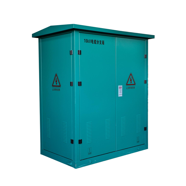
The structural design of the GCK low voltage drawout switchgear relies on standard FA22 or KB profile assemblies. These profiles provide a rigid, dependable framework suitable for standard industrial environments. The mechanical interlocking mechanisms ensure that a drawer cannot be withdrawn while the circuit breaker is in the closed position. Standard drawer sizes typically start at a full unit height, providing ample internal space for standard motor control components. The assembly process is straightforward, relying on bolted connections that offer excellent mechanical stability under normal operating conditions.
Performance parameters for GCK models align perfectly with general industrial requirements. Typical rated currents for the main busbar reach up to 3200A or 4000A. The short-time withstand current capabilities are robust enough to handle standard fault levels in mid-sized manufacturing plants. Standard Ingress Protection (IP) ratings usually range from IP30 to IP40. This level of protection prevents solid objects and tools from contacting live parts, making it highly suitable for clean, indoor electrical rooms.
GCK Technical Parameter | Standard Specification |
|---|---|
Rated Operational Voltage | 380V / 400V / 660V |
Main Busbar Rated Current | Up to 4000A |
Vertical Busbar Rated Current | Up to 1000A |
Rated Short-Time Withstand Current | 50kA / 1s |
Rated Peak Withstand Current | 105kA |
Standard IP Rating | IP30, IP40 |
Configuration priorities dictate where GCK systems excel. They are the ideal choice for environments that do not face severe space constraints. Standard manufacturing plants and basic motor control centers benefit greatly from this architecture. Facilities prioritizing budget and simplicity over maximum circuit density often find GCK to be the most logical choice. The straightforward design means that local maintenance teams can easily troubleshoot and repair the internal components without specialized factory training.
Despite its reliability, the GCK framework has specific limitations and trade-offs. The most notable is spatial inefficiency. Because standard drawers are larger, the system accommodates fewer functional units per vertical section compared to newer iterations. This requires a larger overall cabinet footprint to house the same number of circuits. Additionally, the thermal dissipation limits are lower. The standard profile design does not support the extreme high-density packing of heat-generating components found in more advanced modular systems.
Structural advancements define the GCS low voltage drawout switchgear architecture. This system utilizes 8MF open-type steel profiles. These profiles feature mounting holes pitched at 20mm intervals along all three axes. This extreme modularity allows engineers to configure the internal space with high precision. The most significant advantage is the high-density capacity. A single GCS cabinet can house up to 22 (or more) 1/2-unit drawers. This allows facility managers to pack a massive number of control circuits into a very small physical footprint.
Enhanced electrical stability is engineered directly into the GCS framework. The busbar configurations are heavily optimized for high-stress environments. GCS systems feature a higher short-circuit withstand strength, often utilizing a double-busbar arrangement or heavily braced vertical bus systems. Superior thermal management is critical due to the high density of components. The cabinet design incorporates advanced ventilation pathways and strict phase-to-phase isolation techniques. This ensures that even when fully loaded with 22 operational drawers, the internal temperature rise remains within safe operational limits.
GCS Technical Parameter | Standard Specification |
|---|---|
Rated Operational Voltage | 380V / 400V / 660V |
Main Busbar Rated Current | Up to 4000A (or higher with double bus) |
Vertical Busbar Rated Current | Up to 1000A |
Rated Short-Time Withstand Current | 80kA / 1s |
Rated Peak Withstand Current | 176kA |
Standard IP Rating | IP30, IP40 |
Ideal applications for GCS involve centralized loads requiring absolute reliability. Petrochemical plants, large-scale data centers, and power generation facilities depend on this architecture. These environments demand high density due to the sheer volume of motors and feeders required. Furthermore, GCS is highly adaptable to smart grids. The compact drawers can easily accommodate intelligent relays and communication modules necessary for modern automated power distribution networks.
The trade-offs for this advanced capability involve complexity and initial expenditure. The drawer mechanisms in a GCS system are highly intricate. They require precise mechanical alignment during insertion and extraction. The system has a higher sensitivity to mechanical misalignment; an uneven floor can cause the high-density drawers to bind or jam. Consequently, the elevated initial procurement costs reflect the advanced engineering, tighter manufacturing tolerances, and heavier copper bracing required to build these units.
Evaluating space utilization and cabinet footprint reveals the starkest contrast between the two systems. Drawer modularity directly impacts the total number of cabinets required for a specific single-line diagram. GCK relies heavily on full-unit or larger drawers. If a facility needs to control 40 small motors, a GCK lineup might require four or five vertical sections. GCS utilizes 1/2 and even 1/4 units for small loads. Those same 40 motors could potentially be controlled from just two vertical GCS sections. This spatial efficiency is invaluable in urban infrastructure or offshore platforms where real estate is strictly limited.
Thermal and electrical performance must be analyzed closely. Temperature rise limits dictate how much current can safely pass through the switchgear. GCS employs superior busbar isolation techniques, often embedding the vertical bus in a flame-retardant plastic functional board. This prevents arc propagation and improves fault containment. GCK generally uses a more open vertical bus structure. While effective for standard loads, the GCK design requires more careful load distribution to prevent localized hot spots within the cabinet.
Maintenance strategy, safety, and ergonomics differ significantly. Both systems offer test, isolated, and connected positions for the drawers. However, the physical effort required for drawer insertion and extraction varies. GCS mechanisms often feature a rotary handle that smoothly racks the drawer in and out, providing excellent tactile feedback. The mechanical interlocks are highly reliable, preventing withdrawal under load. GCK mechanisms are robust but can sometimes require more physical force to engage and disengage the primary contacts, especially on larger amperage drawers.
Automation and smart integration readiness separates legacy designs from modern requirements. Modern SCADA systems and intelligent motor controllers require dedicated space for communication wiring. GCS systems are designed with these automated communication interfaces in mind. The cable compartments and auxiliary contact blocks are optimized for Profibus, Modbus, or Ethernet cabling. While GCK can be retrofitted or designed for smart components, the inherent spatial limitations often make clean, organized communication wiring more challenging to execute.
Evaluation Criteria | GCK Switchgear | GCS Switchgear |
|---|---|---|
Structural Profile | FA22 or KB Profile | 8MF Open-Type Profile (20mm pitch) |
Max Drawer Density | Standard (Fewer units per cabinet) | High (Up to 22 1/2-units per cabinet) |
Primary Application | Standard MCC, General Manufacturing | Data Centers, Petrochemical, Smart Grids |
Busbar Isolation | Standard physical separation | Advanced flame-retardant functional boards |
Automation Readiness | Moderate (Requires careful space planning) | High (Optimized for intelligent relays) |
Balancing initial capital expenditure against operational savings is the core of procurement strategy. GCS requires a higher upfront investment. The complex 8MF profiles, specialized rotary mechanisms, and heavy copper bracing drive up manufacturing costs. However, this initial CapEx is often offset by significant operational savings. The smaller footprint reduces electrical room real estate costs. More importantly, the rapid MTTR of the high-density drawers drastically reduces downtime costs over the facility's lifecycle. GCK offers a lower initial CapEx, making it attractive for projects with strict immediate budget constraints.
Specifying custom drawout switchgear requires detailed engineering data. Non-standard ambient temperatures require specific busbar derating calculations. If a facility operates in a high-heat environment, the manufacturer must increase the copper cross-section. Specific seismic ratings dictate heavier frame construction and reinforced anchoring points. Unique busbar materials, such as silver-plated copper or tin-plated aluminum, alter the thermal dynamics. These custom parameters heavily impact the lead times of both GCK and GCS configurations.
Structuring the Request for Quote (RFQ) accurately eliminates bidding discrepancies. A low voltage switchgear manufacturer needs precise project application data to provide an accurate bid. Procurement teams must supply comprehensive single-line diagrams and detailed load schedules. Configuration priorities must be clearly stated—whether the priority is minimizing footprint (favoring GCS) or minimizing initial cost (favoring GCK). Spatial constraints, including ceiling height, door widths, and cable entry points (top or bottom), must be documented in the RFQ.
Vetting a drawout switchgear supplier mitigates long-term operational risks. Critical criteria include verifying ISO quality management certifications. Procurement engineers must request type-test reports from recognized authorities like ASTA, KEMA, or local equivalents. These reports prove the switchgear can actually withstand the stated short-circuit currents. Finally, evaluate the supplier's Factory Acceptance Testing (FAT) capabilities. A rigorous FAT ensures that all mechanical interlocks, electrical clearances, and automated interfaces function perfectly before the equipment ships to the site.
Mechanical alignment is the most critical implementation risk for drawout systems. The floor leveling must be near perfect. In high-density GCS cabinets, even a slight tilt in the concrete pad causes the 8MF frame to warp. This warping leads directly to drawer jamming, especially in the uppermost tiers. Mitigation requires strict civil engineering prep. Installers must use laser-leveled channel steel bases embedded in the concrete. The switchgear must be bolted or welded to this perfectly level base to ensure smooth drawer operation throughout its lifespan.
To ensure proper mechanical alignment during installation, site teams must execute the following steps:
Survey the concrete housekeeping pad using a precision laser level to identify high and low spots.
Install the base channel steel, using steel shims to achieve a level tolerance of less than 1mm per meter.
Weld or bolt the channel steel securely to the concrete foundation to prevent shifting under load.
Position the switchgear sections onto the channel steel, bolting adjacent sections together before securing them to the base.
Test the insertion and extraction of every drawer in the lineup to verify smooth operation before landing any field cables.
Lead times and component standardization present distinct supply chain risks. Sourcing proprietary drawer components can lead to extended downtime if a specific rotary handle or primary contact fails years after installation. Standardized parts mitigate this risk. During the RFQ phase, negotiate comprehensive spare parts packages. Ensure that critical wear items, such as primary isolating contacts and mechanical interlock springs, are kept in local inventory. GCK systems often benefit from wider availability of generic replacement parts compared to the highly specialized GCS mechanisms.
Commissioning and interface challenges frequently delay project handovers. Integrating automated interfaces in GCS systems requires precise termination of communication cables. Shielded cables must be grounded correctly to prevent electromagnetic interference from corrupting SCADA data. Rigorous Site Acceptance Testing (SAT) is mandatory. The SAT must include functional testing of every single drawer, verifying that intelligent motor controllers communicate accurately with the central PLC under simulated load conditions.
Finalize your single-line diagrams and update your load schedules to reflect current operational demands.
Measure your electrical room to define exact spatial constraints, ceiling clearances, and cable entry requirements.
Compile a list of required intelligent communication protocols for your facility's SCADA integration.
Initiate technical consultations with a qualified supplier to determine the exact configuration that meets your operational demands.
A: The main difference lies in drawer density, structural profiles, and thermal stability. GCS uses an 8MF modular profile allowing up to 22 high-density drawers per cabinet, ideal for centralized loads. GCK uses a standard FA22 or KB profile, supporting fewer drawers per cabinet, making it better suited for standard industrial applications.
A: GGD is a fixed-type switchgear requiring full busbar shutdown for maintenance, suitable for simple loads. GCK, GCS, and MNS are all drawout types allowing isolated maintenance. MNS and GCS offer high-density modularity, while GCK provides standard density for general motor control centers.
A: No. The structural frameworks and drawer mechanisms are completely different. GCS relies on an 8MF profile with specific rotary racking mechanisms, while GCK uses different standard profiles and interlocking hardware. Components, primary contacts, and drawer chassis are proprietary to their specific structural standard.
A: GCS is typically preferred for high-density applications. Its ability to utilize 1/2-unit and 1/4-unit drawers allows engineers to pack significantly more motor starters into a single vertical section, drastically reducing the overall footprint required in the electrical room.
A: GCK has a lower initial capital expenditure due to simpler structural profiles and standard drawer mechanisms. GCS requires a higher upfront investment but often yields better long-term operational savings through reduced real estate requirements and faster maintenance turnaround times during faults.
A: Manufacturers require detailed single-line diagrams, comprehensive load schedules, required IP ratings, and short-circuit withstand capacities. They also need to know configuration priorities, spatial constraints of the electrical room, and specific cable entry locations.
A: While both can be equipped with intelligent components, GCS is generally better suited for complex smart grid setups. Its high-density design and advanced cable management compartments easily accommodate the intelligent relays, communication modules, and SCADA wiring required for automated distribution.


