

Views: 0 Author: Site Editor Publish Time: 2026-06-05 Origin: Site


A Power Transformer stands as both the critical bottleneck and the ultimate enabler of modern electrical infrastructure. It bridges the massive gap between high-voltage utility grids and facility-level power requirements. Without it, industrial power distribution simply stops.
While the foundational physics of these devices have remained unchanged for over a century, specifying, operating, and maintaining them represents a high-stakes capital expenditure. Misaligning your operational loads with unit specifications leads to exponential energy waste. It accelerates thermal degradation and triggers catastrophic facility downtime.
This guide moves beyond basic textbook definitions to provide a robust commercial and engineering evaluation framework. We detail exactly how these units operate and pinpoint the true drivers of efficiency losses. You will also learn how to evaluate different architectural models for your specific facility applications, ensuring safe and highly efficient energy management.
Primary Function: Power transformers manipulate voltage and current ratios to enable low-loss, long-distance power transmission and safe, usable facility distribution.
The Efficiency Mandate: While industrial transformers routinely hit 98–99% efficiency, the remaining 1–2% in thermal and magnetic losses dictates the unit’s lifecycle.
Architecture Selection: Choosing between dry-type and oil-immersed transformers requires balancing cooling capacity, physical footprint, and environmental safety regulations.
Predictive Maintenance: Lifespans (typically 30–50 years) are strictly governed by operating temperatures; continuous monitoring of insulation and turns ratios is critical for risk mitigation.
You can easily compare grid transmission to high-pressure municipal water mains. Just as a pressure-reducing valve stops facility pipes from bursting under extreme municipal pressure, a step-down Power Transformer safely converts utility-level electrical "pressure." It drops transmission lines carrying 12,000V or 35kV down to operational voltages like 480V, 240V, or 120V. This step down process keeps machinery, servers, and lighting circuits perfectly safe.
High voltage remains absolutely mandatory for bulk distribution. We must look at the mathematical reality of transmission. According to the power loss equation (P = I⊃2;R), energy loss in a cable scales with the square of the current (I). If you push massive amounts of current through a long wire, the inherent resistance (R) turns that electrical energy into wasted heat. Stepping up the voltage allows you to drastically reduce the current. This delivers the exact same amount of total power to the destination. This mathematical fact makes high-voltage transmission the only commercially viable method to move power across geographic distances. Otherwise, utility grids would suffer massive thermal waste.
Beyond simple voltage adjustment, these units provide critical electrical isolation. They physically separate operational facility circuits from utility-side ground faults. This secondary function acts as an invisible firewall. It protects highly sensitive industrial equipment from sudden grid surges, effectively isolating internal networks from unpredictable utility fluctuations.
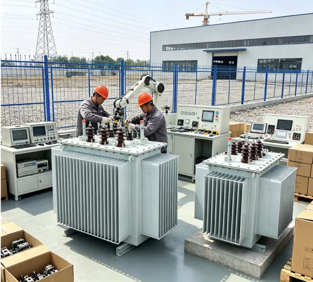
Electromagnetic induction, defined by Faraday’s Law, drives the entire transformation process. Alternating current (AC) enters a primary winding coil. As this current flows, it creates a rapidly fluctuating magnetic field inside a highly engineered steel core. This changing magnetic flux travels through the core and intersects with a secondary winding coil. The moving magnetic field then induces a proportionate voltage inside that secondary coil. The device transfers immense amounts of power between two isolated circuits without any physical or electrical connection between them.
The exact ratio of wire wraps between the primary and secondary coils dictates the outcome. We call this the turns ratio (N&sub1;/N&sub2;). It determines the exact voltage step-up or step-down magnitude. For example, if your primary coil has 2500 wraps and your secondary coil has 100 wraps, you have a 25:1 turns ratio. This specific configuration perfectly converts a 12kV grid input down to a 480V industrial output.
You must also understand the AC limitation. These devices inherently require alternating current to function. Inputting direct current (DC) produces a flat, stationary magnetic field. A static field yields zero changing magnetic flux. Therefore, DC will never induce power transfer across the coils. You must use a separate piece of hardware, known as an inverter, to convert DC into AC before feeding it into the primary windings.
We categorize these units primarily by their specific functionality on the grid. Distribution transformers act as the final-stage step-down units. They typically range from 16 kVA up to 3500 kVA. Engineers design them for extreme longevity and reliability under highly variable consumer load levels. They sit outside commercial buildings or on utility poles, quietly feeding usable power to end-users.
Current transformers (CT), or instrument transformers, serve a distinctly different purpose. They act as specialized isolation units. They step down massive grid currents to very small, manageable levels. We use them strictly for precise power metering and safety relay protection. They ensure monitoring equipment does not blow up from direct high-voltage exposure.
When specifying a primary Power Transformer for a facility, you must choose between dry-type and oil-immersed architectures. Each carries distinct operational trade-offs.
Architecture Type | Insulation Medium | Primary Advantages | Primary Disadvantages | Ideal Applications |
|---|---|---|---|---|
Oil-Immersed | Mineral Oil / Synthetic Ester | Superior thermal dissipation; allows for massive kVA ratings and highly efficient cooling. | High fire risk profile; requires expensive concrete containment infrastructure for leak mitigation. | Outdoor utility pads; high-load heavy industrial manufacturing zones. |
Dry-Type | Ambient Air / Cast Epoxy Resin | Zero fluid leak risks; drastically reduced fire hazards; easy indoor deployment. | Larger physical footprint for the same kVA rating; sensitive to harsh particulate and dust. | Indoor commercial high-rises; schools; clean manufacturing floors. |
Oil-immersed models utilize specialized mineral oil or synthetic ester fluids for both insulation and cooling. They offer superior thermal dissipation. Fluid actively circulates around the coils, pulling heat away much faster than air. This fluid dynamic allows for higher efficiency limits and massive kVA ratings. However, they require extensive containment infrastructure. If the tank ruptures, you face severe environmental leak mitigation and a high fire risk profile.
Dry-type models utilize ambient air and solid cast epoxy resins for internal insulation. They completely eliminate fluid leak risks and drastically reduce fire hazards. You can safely install them inside high-rise buildings, schools, or manufacturing floors. However, they demand a generally larger physical footprint for the exact same kVA rating compared to liquid-filled units. They also remain highly sensitive to harsh, unconditioned environmental particulate.
Top-tier Power Transformer models routinely achieve efficiency ratings well above 98%. In large utility applications, they often hit 99.5%. However, you cannot ignore the remaining fractional losses. These seemingly small inefficiencies compound massively over a standard 30-year operational lifecycle. They waste significant amounts of energy and generate destructive internal heat.
We divide these efficiency drains into two specific engineering categories: load losses and no-load losses.
Core Losses (No-Load / Iron Losses): These energy drains remain absolutely constant. They happen continuously as long as the device remains energized, entirely independent of your facility's actual power load. They stem directly from the magnetic core. Core losses include hysteresis, which is the microscopic magnetic friction generated as the AC field constantly reverses direction. They also include eddy currents, which are unintended localized currents swirling inside the steel. Specifying high-quality laminated silicon steel cores minimizes this baseline waste.
Winding Losses (Load / Copper Losses): These represent variable I⊃2;R heat losses within the internal copper or aluminum coils. They scale directly with your facility's real-time power demand. When your factory floor ramps up production and draws more current, winding losses increase exponentially, generating immense internal heat.
Heat remains the ultimate enemy of electrical longevity. The Arrhenius equation establishes a strict, undeniable engineering benchmark. For every 7 to 10°C increase in continuous operating temperature above the baseline design threshold, the lifespan of the internal insulation is cut exactly in half. Proper kVA sizing, aggressive ambient ventilation, and routine cooling system maintenance are simply non-negotiable if you want the unit to survive its intended decades of service.
Installation and commissioning carry immense initial risks. Proper setup prevents immediate catastrophic failure. You must meticulously verify matching polarity and complex phase configurations. You must ensure Delta or Wye connections align perfectly with your internal facility infrastructure. You must also set appropriate Voltage Adjustment Taps. These internal taps allow you to slightly alter the turns ratio. This handles utility-side voltage fluctuations safely before you energize the main load.
Once operational, facilities must immediately move away from outdated "run-to-fail" maintenance models. We strongly recommend implementing specific, scheduled health audits to defend your capital expenditure.
Transformer Turns Ratio (TTR) Validation: This test confirms the primary and secondary coils maintain their exact factory-specified ratio. It proves no internal shorts have bypassed any coil wraps.
Insulation Resistance Mega-ohm Testing: This diagnostic applies a high DC voltage to measure the resistance of the internal insulation. High resistance proves the insulation remains healthy; low resistance warns of impending short circuits.
Power Factor Assessments: This test measures overall dielectric health. It spots moisture intrusion or early-stage insulation breakdown long before it causes a localized failure.
Dissolved Gas Analysis (DGA): For oil-immersed units, this remains the gold standard. Drawing a fluid sample and analyzing it for specific trace gases detects invisible internal arcing, paper degradation, or severe localized overheating.
Visual Breather Inspections: Technicians must routinely check silica gel breathers. As the internal oil expands and contracts, the tank "breathes" outside air. The silica gel removes moisture. If the gel changes color, it is saturated, risking severe moisture ingress into the insulating fluid.
Finally, you must enforce rigid safety protocols. Strict compliance with LOTO (Lockout/Tagout) procedures is legally and ethically mandatory. High voltage kills instantly. Facilities must also rely on automated physical fail-safes. Buchholz relays, installed exclusively on liquid-filled units, detect sudden internal gas buildup from electrical faults. They automatically trip the breaker and isolate the unit long before the tank can catastrophically rupture or explode.
A well-specified Power Transformer does much more than simply alter utility voltage. It directly dictates the baseline energy efficiency, the overall physical safety, and the future scalability of your entire facility's electrical footprint.
Engineering and procurement leaders must actively audit their current facility capacity limits against their existing hardware. You must evaluate your physical environment carefully to determine the long-term suitability of Dry-Type versus Oil-Immersed architectures. Making the wrong choice leads to endless compliance headaches and thermal degradation.
Implement aggressive predictive testing protocols immediately. Move past visual inspections and invest in routine DGA and TTR validation. Taking these action-oriented steps will permanently defend your capital investment and eliminate unexpected operational downtime.
A: They hum due to a physical phenomenon called magnetostriction. As alternating current flows through the coils, the resulting changing magnetic field causes the steel core laminations to physically expand and contract. In a standard 60Hz electrical system, these microscopic physical shifts happen exactly 120 times per second, creating the characteristic, continuous buzzing sound.
A: With optimal thermal management and routine predictive maintenance, standard lifespans run between 30 and 50 years. This longevity is largely dictated by the structural integrity of the internal paper and oil insulation. Because excessive heat degrades this insulation rapidly, operating temperatures and aggressive cooling remain the primary factors in a unit’s survival.
A: No. They only step alternating current (AC) voltage up or down via magnetic flux. Direct current (DC) produces a flat, stationary magnetic field, which cannot induce any current in the secondary coil. Converting DC power to AC power requires a completely distinct piece of electronic hardware called an inverter.


