

Views: 0 Author: Site Editor Publish Time: 2026-09-02 Origin: Site


Electrical distribution failures carry massive operational costs. When an under-specified low voltage switchgear panel fails under load, you face immediate facility downtime and severe safety hazards. Selecting the right electrical panel goes beyond matching voltage and amperage capacities. You have to balance mechanical fault protection, thermal mitigation, and your facility's specific maintenance schedule.
Facility managers and electrical engineers must look past basic nameplate ratings. Evaluating structural designs, safety compliance standards, and component modularity guarantees long-term operational continuity. A poorly designed enclosure or inadequate busbar system leaves your infrastructure vulnerable to arc flashes, overheating, and prolonged outages during routine maintenance. By understanding the features that differentiate standard panels from high-performance systems, you ensure the selected equipment protects your operators and keeps your production lines running.
Compliance with stringent design verification standards (such as IEC 61439) is the non-negotiable baseline for ensuring thermal stability and mechanical safety under fault conditions.
The architectural choice between a fixed and a drawout configuration fundamentally dictates a facility’s Mean Time To Repair (MTTR) and lifecycle maintenance costs.
Internal compartmentalization (Forms of Separation) directly impacts operator safety and the ability to isolate faults without dropping power to the entire facility.
Selecting a reliable low voltage switchgear manufacturer requires rigorous vetting of their Factory Acceptance Testing (FAT) protocols and supply chain transparency.
The primary role of any low voltage electrical panel is to act as the centralized nervous system for facility power. It must safely control power flow, provide immediate circuit protection, and physically separate faulty components while ensuring continuous power delivery to unaffected zones. When a downstream fault occurs, the panel must isolate the issue instantaneously without cascading the failure to the main incoming breaker. Proper breaker coordination ensures that only the breaker closest to the fault trips, leaving the rest of the facility online.
Baseline operational parameters define the physical and electrical limits of the equipment. These systems typically manage voltage ranges up to 1000V AC or 1500V DC. Precise evaluation of rated current capacities ensures the main busbars and incoming breakers can handle peak operational loads without exceeding thermal limits. Short-circuit withstand capacity is a critical metric. The panel must physically contain the massive electromagnetic forces and thermal energy generated during a severe power surge, preventing busbar deformation and catastrophic enclosure rupture.
To verify a panel's operational reliability under fault conditions, engineers typically execute the following evaluation sequence:
Calculate the maximum available fault current at the main incoming terminals based on the upstream transformer impedance.
Verify the short-circuit withstand rating (Icw) of the main busbar system exceeds the calculated fault current for a specified duration, usually 1 to 3 seconds.
Confirm the short-circuit making capacity (Icm) of the incoming circuit breakers to ensure they can safely close into an existing fault without exploding.
Review the mechanical bracing of the busbar supports to ensure they can withstand the peak electromagnetic forces generated during the first half-cycle of a fault.
Check the thermal withstand capabilities of the insulation materials surrounding the live conductors.
Verifying the safety and performance of a 400V low voltage distribution cabinet relies heavily on strict adherence to IEC 61439 standards or regional equivalents. This standard dictates rigorous design verification processes, ensuring the assembly can withstand specified short-circuit currents, maintain dielectric properties, and manage temperature rises effectively under full load conditions. Equipment lacking verified IEC compliance introduces unacceptable risk into the electrical network. Inspectors look for type-test certificates from independent laboratories to confirm the manufacturer's claims.
Grounding protocols establish the foundation of operator safety during active maintenance and switching operations. A continuous, adequately sized earth busbar must run the entire length of the switchgear, ensuring all exposed conductive parts remain safely grounded. The earth bar must be rated to carry the maximum earth fault current until the protection devices clear the fault.
Beyond standard mechanical barriers, modern safety technologies elevate operator protection significantly. Integrating active arc flash mitigation relays detects the light and pressure of a developing arc in milliseconds, tripping the upstream breaker before the energy reaches lethal levels. Remote racking systems further remove operators from the arc flash boundary, allowing them to engage or disengage breakers from a safe distance using a motorized umbilical control. Infrared (IR) viewing windows installed on the rear covers allow thermographers to scan busbar joints for hot spots without opening energized compartments.
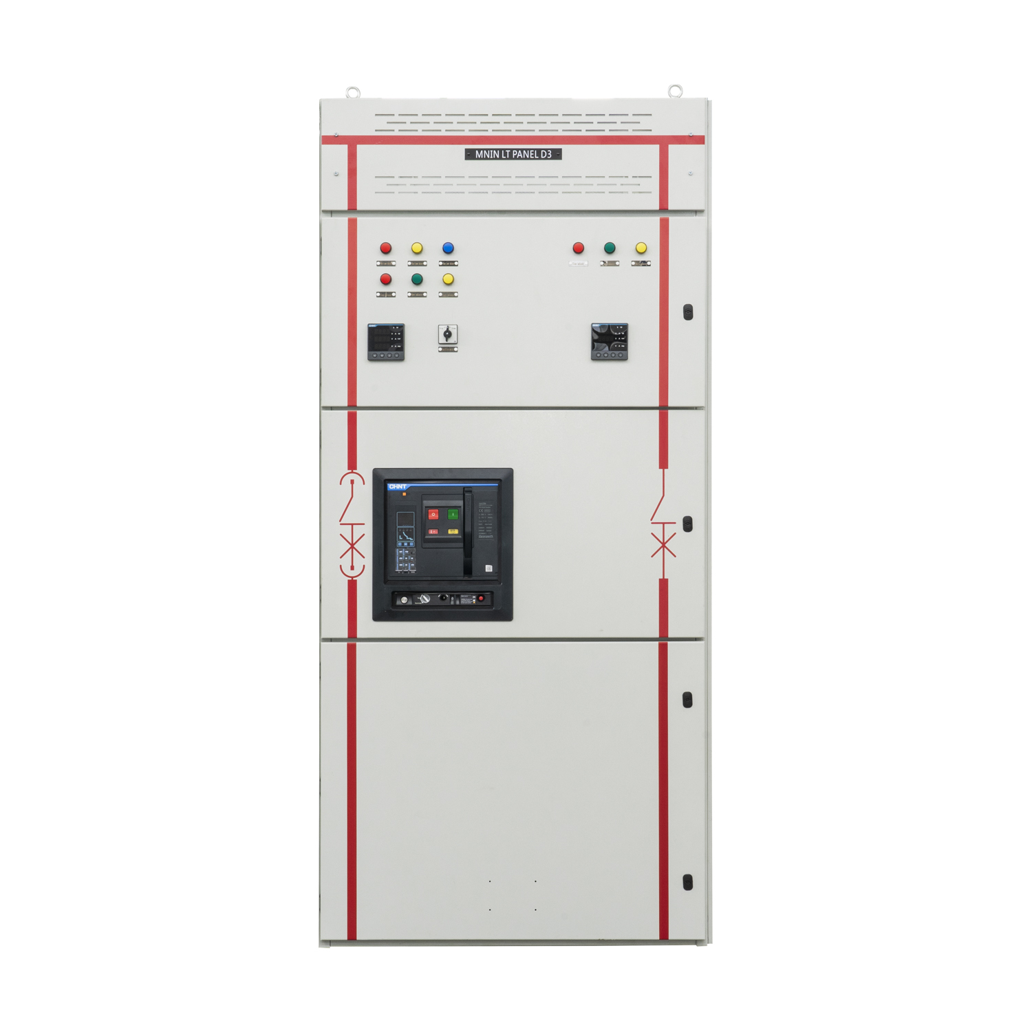
The structural mechanics of a fixed low voltage switchgear cabinet rely on permanently installed components. Circuit breakers, contactors, and protection relays are bolted directly to the internal mounting plates and hardwired to the main busbar system. Because the components lack mobility, the internal architecture remains straightforward, reducing the number of moving mechanical parts that could potentially fail over time. Installers use calibrated torque wrenches to secure every busbar connection, applying torque marks to visually verify that joints have not loosened due to thermal cycling or vibration.
This configuration offers a highly compact physical footprint. Facilities with predictable loads and infrequent maintenance schedules often benefit from this streamlined approach. The trade-offs become apparent during maintenance cycles. Replacing a faulty breaker or conducting routine testing requires complete de-energization of the main busbar. This leads to higher operational downtime and requires complex isolation procedures to ensure the panel is entirely dead before technicians can safely open the doors and begin unbolting components. Lockout/Tagout (LOTO) procedures take significantly longer, as operators must verify zero energy across the entire section before commencing work.
A drawout low voltage switchgear cabinet utilizes a highly modular design characterized by a dual-layer architecture. Permanent metal enclosures house specialized cassettes or cradles, allowing the actual circuit breakers to be mechanically racked in and out. This disengageable design means a specific breaker can be isolated, tested, or completely removed while the main busbar remains fully energized and operational. Automatic safety shutters drop down over the live busbar stabs the moment the breaker is racked out, preventing accidental contact with live parts.
The primary value of the drawout configuration is the drastic reduction in Mean Time To Repair (MTTR). It is the standard choice for continuous manufacturing plants, hospitals, and data centers where downtime carries severe financial or life-safety penalties. Operators can swap a faulty breaker with a spare in minutes rather than hours. The trade-offs include a larger physical footprint to accommodate the racking mechanisms and the presence of complex mechanical interlocks that require skilled, trained operation to prevent accidental engagement under load.
Feature Comparison | Fixed Configuration | Drawout Configuration |
|---|---|---|
Component Mounting | Bolted directly to chassis and busbars. | Mounted in a racking cassette/cradle. |
Maintenance Outage | Requires full busbar de-energization. | Allows localized isolation while bus remains live. |
Mean Time To Repair (MTTR) | High (Hours to Days). | Low (Minutes). |
Physical Footprint | Compact, high-density layout. | Larger footprint due to racking mechanisms. |
Safety Mechanisms | Relies on dead-front covers and LOTO. | Features automatic safety shutters and mechanical interlocks. |
The physical enclosure acts as the first line of defense against environmental degradation and internal faults. Evaluating metal enclosure thickness and structural rigidity is necessary to ensure the panel can withstand both ambient industrial conditions and internal arc pressures. Ingress Protection (IP) ratings must be carefully matched to the installation environment. A clean electrical room may only require IP31, while panels installed in dusty, moisture-heavy, or corrosive industrial environments demand IP54 or higher to prevent premature component failure. Heavy-duty lifting lugs and reinforced base channels are required to handle the immense weight of the switchgear during site rigging and installation.
Internal compartmentalization, defined by Forms of Separation, dictates how fault propagation is managed. Physical barriers between busbars, functional units, and external terminals protect personnel during isolation procedures. Selecting the correct form directly impacts how safely an electrician can work on a specific outgoing circuit while the rest of the board remains live.
Form of Separation | Internal Configuration | Primary Application |
|---|---|---|
Form 1 | No internal separation. Busbars and functional units share the same space. | Small, non-critical distribution boards requiring full shutdown for access. |
Form 2 (2a/2b) | Busbars are separated from functional units. | Standard commercial buildings where basic operator protection is needed. |
Form 3 (3a/3b) | Busbars separated from units; units separated from each other. | Industrial plants requiring isolation of individual circuits during maintenance. |
Form 4 (4a/4b) | Busbars, units, and terminal connections are all individually separated. | Mission-critical facilities demanding maximum safety and zero downtime during localized repairs. |
The main busbar system is the central artery of the switchgear. The choice between copper and aluminum busbars fundamentally impacts performance. Copper offers superior electrical conductivity, lower thermal expansion, and higher resistance to lifecycle degradation and oxidation. Contractors prefer copper for high-amperage applications because it requires less physical space to achieve the required current rating. Aluminum provides a lighter-weight alternative that reduces structural load but requires larger cross-sectional areas to achieve the same current-carrying capacity. Aluminum joints demand strict preparation, including wire brushing and the application of joint compound, along with Belleville washers to maintain contact pressure during thermal expansion.
Thermal management is equally critical. High-load scenarios generate significant heat that must be dissipated to prevent insulation failure. Passive ventilation strategies rely on engineered louvers and natural convection, which works well for standard loads. For high-density configurations, active thermal monitoring systems utilize continuous temperature sensors on critical busbar joints. These systems trigger cooling fans or alert operators before thermal limits are breached, preventing unexpected tripping or equipment damage. Proper phase spacing and the use of non-magnetic materials around single-core cable entries prevent eddy currents from generating localized hot spots.
Modern switchgear has evolved from passive mechanical protection into active, data-driven infrastructure. Assessing the integration of digital protection relays, smart meters, and IoT-enabled sensors provides a clear picture of the panel's connectivity. Digital relays offer highly programmable trip curves, allowing for precise coordination with upstream and downstream devices to ensure only the faulted circuit clears. Communication protocols like IEC 61850 or Modbus TCP allow these relays to integrate seamlessly into the facility's overarching SCADA system.
This connectivity enables the transition from reactive fault clearing to predictive maintenance. IoT sensors continuously monitor environmental humidity, ambient temperature, and mechanical wear on breaker contacts. Real-time alerts notify facility managers of abnormal thermal wear or mechanical degradation long before a physical failure occurs. This data-driven approach allows maintenance teams to schedule targeted interventions during planned outages, maximizing overall facility uptime. Power quality meters track harmonic distortion and voltage sags, providing engineers with the data needed to install active harmonic filters or capacitor banks.
Opting for off-the-shelf, standardized configurations offers distinct operational advantages. These panels are fully type-tested, meaning the exact assembly has already passed rigorous laboratory testing for short-circuit limits and temperature rise. The primary benefits include significantly faster lead times, proven field reliability, and lower upfront engineering costs since the design work is already complete. Installers benefit from standardized termination zones and predictable footprint dimensions, making electrical room layout planning straightforward.
Standardized panels present limitations when integrating into legacy infrastructure. Older facilities often feature restrictive spatial dimensions, unique trenching layouts, or specific top-and-bottom cable entry requirements that standard modular enclosures simply cannot accommodate without extensive on-site modification. Forcing a standard panel into a non-standard space often leads to compromised cable bending radii and restricted airflow.
Certain operational environments make standard solutions unviable. Specifying custom low voltage switchgear becomes necessary when retrofitting restricted spatial footprints where standard dimensions will not fit. Custom engineering allows for non-standard cable entry and exit points, specialized busbar routing to match existing transformers, and highly specific SCADA system integration using proprietary communication protocols. Engineers can design custom transition sections to mate new switchgear directly to existing legacy busducts.
Customization requires additional engineering hours, specialized fabrication, and potentially new type-testing to verify the unique design. While this increases the initial lead time, the long-term installation efficiency, seamless site integration, and optimized operational workflow often outweigh the upfront hurdles. Custom panels can be engineered with specific paint finishes for highly corrosive environments or reinforced frames for high-seismic zones.
Partnering with an unverified supplier introduces severe project risks. Unverified performance claims can lead to catastrophic equipment failure under peak load, or result in non-compliance with local safety codes, forcing costly post-installation modifications. A panel that fails a local electrical inspection will halt a project indefinitely until the violations are corrected.
Mitigating this risk requires demanding comprehensive, transparent documentation from the low voltage switchgear manufacturer. Do not accept internal testing reports alone. Insist on independent laboratory testing certificates that verify short-circuit withstand limits, dielectric properties, and temperature rise tests. Reviewing their historical project portfolio and verifying their ISO quality management certifications provides further assurance of their manufacturing consistency. Inspect their fabrication process to ensure they use high-quality copper plating and robust powder-coating techniques.
Even well-designed equipment can derail a project if supply chain logistics and site integration are mismanaged. Project delays frequently occur due to specialized component shortages or improper alignment between the manufactured panel and the physical site conditions. Large switchgear lineups must often be split into shipping sections, requiring careful coordination to ensure they fit through site access doors and can be reassembled correctly.
To mitigate these risks, standardize internal components using globally recognized brands to ensure local availability for future spares. Implement rigorous Factory Acceptance Testing (FAT) to verify all mechanical interlocks, breaker operations, and electrical functions before the equipment leaves the facility. Follow this with strict Site Acceptance Testing (SAT) protocols, establishing clear demarcations of installation responsibilities between the manufacturer, the logistics provider, and the on-site electrical contractor. Verify that all shipping splits include the necessary splice plates and hardware for field assembly.
Request detailed single-line diagrams, independent type-test certificates, and comprehensive FAT procedures from shortlisted manufacturers to begin the technical evaluation phase.
Calculate your facility's acceptable Mean Time To Repair (MTTR) to determine if a fixed or drawout architecture fits your operational model.
Audit your installation environment to specify the correct Ingress Protection (IP) rating and Form of Separation.
Standardize internal components like breakers and relays across your facility to streamline future spare parts procurement.
A: These panels are typically rated for operations up to 1000V AC or 1500V DC. They are engineered to handle centralized power distribution, safely controlling electrical flow and providing immediate circuit protection across commercial and industrial facilities.
A: It allows individual circuit breakers to be safely isolated, mechanically removed, and replaced without de-energizing the entire main busbar. This modular design drastically reduces maintenance downtime, making it ideal for continuous operations.
A: Switchgear generally features individually compartmentalized breakers, higher short-circuit withstand ratings, and rear access for maintenance. Switchboards are typically front-access, group-mounted, and utilized for lower fault-current applications in less demanding environments.
A: It guarantees the assembly has passed rigorous, standardized design verification tests. These tests confirm the panel's ability to manage temperature rise, maintain dielectric properties, and withstand severe short-circuit forces, ensuring baseline safety and operational reliability.
A: While heavily dependent on environmental conditions and operational load, comprehensive preventative maintenance is typically mandated annually or bi-annually by facility safety codes. This process usually requires a planned outage to safely inspect and torque fixed connections.
A: Lead times are primarily extended by engineering design approval cycles, non-standard enclosure fabrication, and the procurement of specialized breakers. Highly customized designs may also require new, specific type-testing procedures before the equipment can be legally shipped.


