

Views: 0 Author: Site Editor Publish Time: 2026-06-01 Origin: Site


A Power Transformer is a static electrical device. It is critical for modern energy infrastructure. It scales voltage up or down across grid-level transmission networks. It performs this massive energy conversion without altering the electrical frequency. Selecting the right unit goes far beyond simply matching basic voltage requirements. The selection process represents a complex engineering balance. Buyers must weigh upfront capital expenditure against long-term operational efficiency. They must prioritize grid resilience. They also need to meet increasingly strict environmental compliance mandates.
Think of municipal water mains. They require heavy-duty pressure regulators before water safely reaches localized home plumbing. Without these regulators, pipes would burst instantly from the extreme pressure. Similarly, high-voltage electricity requires precise step-down transformation. You must reduce voltage safely before it enters regional distribution networks. Without this critical step, you risk catastrophic system overload and widespread electrical fires. A properly specified unit prevents these surges. It ensures safe, continuous industrial power distribution.
In this comprehensive guide, you will learn how these high-capacity units operate in real-world grid scenarios. We will explore internal core components. You will discover how to evaluate advanced cooling systems. We will also outline the primary energy losses impacting your long-term operational budgets.
System-Level vs. Localized Load: Power transformers are engineered for large-scale energy transmission operating near maximum load, distinguishing them from highly variable, localized distribution transformers.
Thermal Management Dictates Lifespan: An industry-standard rule of thumb dictates that transformer insulation life halves for every 7°C to 10°C increase in operating temperature, making cooling system evaluation paramount.
ESG and Compliance Are Driving Innovation: Modern specifications increasingly favor biodegradable ester oils over traditional mineral oils for enhanced fire safety and environmental compliance, particularly in renewable energy integrations.
At its core, a Power Transformer operates purely on Faraday’s Law of electromagnetic induction. Alternating current (AC) enters the primary winding. This moving current creates a highly fluctuating magnetic flux. The magnetic field then travels through the metallic core. It eventually induces a proportional voltage in the secondary winding. You change the output voltage simply by altering the turns ratio between these two sets of copper windings.
In an ideal physics model, we assume zero energy loss during this transfer. However, real-world deployment presents harsh physical constraints. Engineers must actively manage leakage flux. Some magnetic energy always escapes into the surrounding air. They also must counteract inherent winding resistance. Furthermore, constant magnetic reversal creates molecular friction within the core itself. You must manage these realities to maintain optimal grid efficiency.
Grid placement heavily influences your required specifications. Standard operating tiers handle very different stages of national power delivery. Here are the primary voltage classifications:
110kV to 220kV: Operators rely on these units for regional distribution. They form the backbone of long-haul transmission across varied state terrains.
420kV to 750kV: Utilities deploy these massive units for backbone cross-regional grid connections. They enable transcontinental energy transfers between different national grids.
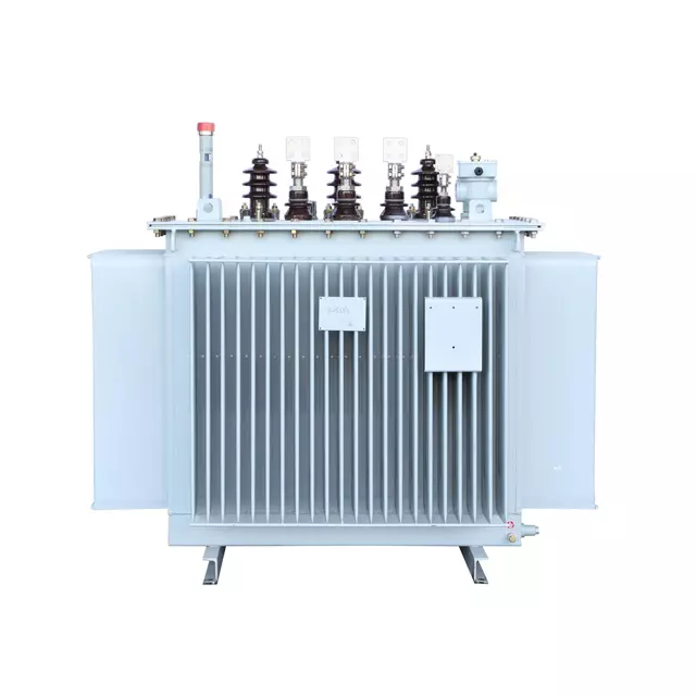
Electrical efficiency begins deep within the physical structure. The core and windings establish your ultimate performance baseline. Manufacturers build modern cores from laminated, low-carbon silicon steel. This specific material construction minimizes destructive eddy currents. You also must choose between copper and aluminum windings. Copper provides superior electrical conductivity. It also allows for a much smaller tank footprint. Aluminum offers a significantly lighter weight. It also provides lower upfront material costs.
Lifespan preservation depends entirely on your cooling systems and internal insulation. As operating temperatures rise, cellulose insulation degrades rapidly. The Arrhenius equation supports the rule that insulation life halves for every 7°C to 10°C rise. You must map specific cooling classes to your exact operational environments. We follow stringent IEEE and IEC standards for thermal management.
Here is a breakdown of common cooling classes and their specific mechanisms:
Cooling Class | Cooling Mechanism | Ideal Use Case |
|---|---|---|
ONAN | Oil Natural Air Natural | Standard outdoor utility substations operating under normal loads. |
ONAF | Oil Natural Air Forced | Substations requiring supplementary cooling via external fan banks. |
OFAF | Oil Forced Air Forced | High-capacity transmission networks operating under heavy continuous stress. |
Modern engineering designs often transition away from traditional cellulose paper and mineral oil. You might select resin-cast dry-type systems for indoor facilities. Alternatively, you might deploy ester oil-immersed setups. These modern fluids provide superior thermal management capabilities.
Safety and monitoring mechanisms prevent catastrophic failures. They protect your massive infrastructure investments from sudden grid anomalies.
Tap Changers: On-Load Tap Changers (OLTC) allow dynamic voltage regulation. They do this without service interruption. No-Load Tap Changers (NLTC) require you to completely disconnect the unit before making manual voltage adjustments.
Early Fault Detection: Buchholz relays serve an absolutely critical safety role. They detect dangerous gas buildup. This gas results from internal oil degradation and localized electrical arcing.
Isolation and Maintenance: You must install robust Load Break Switches. Proper explosion venting is also mandatory. It ensures operational safety during extreme internal pressure events.
A high-voltage Power Transformer adapts to vastly different industrial landscapes. Utility substations represent the most common global application. Generation plants use step-up applications. They push freshly generated electricity onto high-voltage long-haul lines. Conversely, municipal grid handovers rely on step-down applications. They reduce transmission voltage for safe regional distribution.
Harsh physical environments demand highly specialized equipment. Mining operations often take place in volatile, gas-heavy subterranean environments. Standard equipment poses severe explosion risks here. You need hermetically sealed isolation transformers built to ATEX standards. These specialized units prevent electrical arcs from igniting ambient combustible gases.
Renewable energy integration presents entirely unique operational challenges. Solar arrays and wind farms generate highly variable loads. This erratic power input severely stresses internal metallic components. Ester oil-immersed transformers excel in these demanding environments. They provide exceptionally high flash points compared to traditional mineral fluids. Ester oils are also fully biodegradable. This aligns perfectly with modern ESG mandates. It dramatically reduces ecological damage during accidental fluid spills.
Every transformer experiences measurable energy losses during continuous operation. Understanding these mechanical and electrical inefficiencies helps you evaluate long-term financial drains. You must account for these variables during the initial procurement phase.
Copper losses depend entirely on the active electrical load. Engineers often refer to these as I⊃2;R losses. They occur because winding materials possess inherent electrical resistance. As your network power load increases, copper losses multiply exponentially. You lose this electrical energy entirely as radiating heat.
Core losses remain completely fixed regardless of the electrical load. They stem from two primary electromagnetic phenomena:
Hysteresis Loss: Alternating currents continuously realign magnetic domains within the steel core. This constant molecular friction consumes electrical energy. It also generates significant internal heat that your cooling system must dissipate.
Eddy Current Loss: The alternating magnetic field induces circular stray currents inside the core material. Manufacturers mitigate this effect by using extremely thin steel laminations instead of solid metal blocks.
Smart procurement requires evaluating capital expenditure against operational expenditure. You might save your budget on upfront unit costs. However, high core and copper losses drain your finances over a 30-year lifecycle. A highly efficient unit often justifies a premium initial price. It repays this premium through decades of compounding energy savings.
Specifying a high-voltage unit requires strict technical alignment. Always begin with thorough nameplate verification. You must audit the kVA rating. You must verify primary and secondary voltages. You must double-check impedance values, phase counts, and cooling classes. Any mismatch here can destabilize your entire regional grid infrastructure.
Site preparation involves major civil and mechanical realities. These units weigh tens of thousands of pounds. You must plan for complex transportation logistics. This often involves specialized rail cars, reinforced flatbeds, and massive commercial cranes. You must also build rigorous foundational padmount structures. Fluid containment compliance is strictly non-negotiable. You must construct adequate concrete spill prevention berms. These berms capture potential oil leaks before they contaminate local soil and groundwater.
Finally, you must build supply chain resilience into your project timeline. Custom high-voltage units require notoriously long manufacturing cycles. Lead times can easily stretch beyond a full calendar year. Always mandate a comprehensive Factory Acceptance Testing (FAT) protocol. You must verify all performance data under simulated loads. Tests should include heat run evaluations and lightning impulse tests. Do this before authorizing physical site delivery.
A robust Power Transformer serves as the central anchor of infrastructure reliability. Successful specification requires deep technical diligence. Keep these crucial final steps in mind before finalizing your infrastructure upgrades:
Look far beyond baseline voltage needs when shortlisting equipment.
Thoroughly evaluate internal cooling capabilities and insulation types to maximize equipment lifespan.
Calculate fixed and variable operational losses strictly over a 30-year operational horizon.
Ensure complete environmental compliance, especially regarding insulating fluids and spill containment.
Audit your current grid architecture alongside specialized engineering teams before drafting your final RFP.
A: Power transformers handle system-level transmission networks. They operate continuously near 100% maximum load to move massive amounts of high-voltage energy across long distances. Distribution transformers step down voltage for end consumers. They handle localized, highly variable loads and operate at much lower voltages across fluctuating daily demand cycles.
A: Thermal degradation of internal insulation remains a primary culprit. Operating temperatures exceeding design limits rapidly destroy paper insulation. Oil contamination and moisture ingress also severely compromise dielectric strength. Additionally, external lightning strikes and switching surges can physically destroy internal windings if protective surge arresters fail.
A: Ester fluids provide significant safety and ESG benefits. They boast much higher flash points, making them heavily resistant to catastrophic fire ignition. Furthermore, ester oils are completely biodegradable. If a tank ruptures, the fluid naturally breaks down, mitigating severe environmental risks and avoiding costly soil remediation efforts.


