

Views: 0 Author: Site Editor Publish Time: 2026-09-09 Origin: Site


In critical power distribution, the physical architecture of your low voltage switchgear dictates upfront capital expenditure, long-term facility uptime, maintenance safety, and operational resilience. Facility managers and electrical engineers must balance strict footprint constraints against the operational necessity for rapid fault recovery, serviceability, and safe maintenance. Choosing the wrong configuration leads to unnecessary upfront costs or unacceptable maintenance downtime.
This guide provides a direct, technical comparison of fixed vs drawout switchgear architectures. We evaluate mechanical design, breaker types, lifecycle maintenance, and application suitability to inform your procurement strategy. You will see exactly how bolted connections compare to racking mechanisms in real-world scenarios, allowing you to align your electrical infrastructure with your facility's exact reliability requirements.
Maintenance & Uptime: Drawout switchgear allows for the rapid replacement of circuit breakers without de-energizing the entire bus, drastically reducing Mean Time to Repair (MTTR) compared to fixed configurations.
Cost & Footprint: Fixed switchgear requires a significantly lower initial capital investment and occupies a smaller physical footprint, making it ideal for facilities where space is premium and continuous uptime is not mission-critical.
Safety & Isolation: Drawout designs inherently provide superior physical isolation during maintenance, reducing arc flash exposure risks for personnel.
Standardization: Understanding specific cabinet standards—such as GGD for fixed, and GCK/GCS for drawout—is critical when evaluating proposals from a low voltage switchgear manufacturer.
Low voltage switchgear functions as the central nervous system of a facility's electrical distribution network. Typically rated up to 1000V AC, this equipment consists of a centralized assembly of circuit breakers, fuses, switches, and protective relays. Its primary mandate is to control, protect, and isolate electrical equipment downstream, ensuring that faults are cleared rapidly without cascading through the entire electrical grid.
Accurate procurement terminology prevents costly specification errors. Engineers often use the terms switchgear and switchboards interchangeably, but they represent entirely different classes of equipment. Switchboards rely on basic circuit breakers and group-mounted, front-accessible designs. They are engineered for lower costs and standard commercial applications. Switchgear features individually compartmentalized breakers, sophisticated microprocessor-based relays, advanced power monitoring systems, and superior fault-detection capabilities. Switchgear withstands higher short-circuit currents and offers a much higher degree of internal separation.
Feature | Low Voltage Switchgear | Standard Switchboards |
|---|---|---|
Breaker Mounting | Individually compartmentalized (Fixed or Drawout) | Group mounted, panelboard style |
Fault Tolerance | High short-circuit withstand ratings (up to 100kA+) | Moderate short-circuit ratings |
Internal Separation | High (Form 3 or Form 4 barriers) | Low (Form 1 or Form 2) |
Maintainability | Rear or front access, highly serviceable | Typically front access only, limited serviceability |
Primary Application | Industrial plants, data centers, main utility service | Commercial buildings, light retail, secondary distribution |
The primary mechanical divergence in switchgear design lies in how the active switching devices interface with the main power bus. This interface dictates the level of serviceability the equipment provides. In a fixed configuration, components are permanently bolted to the busbar. In a drawout configuration, components are mounted on specialized racking mechanisms, allowing them to be physically disconnected and removed while the main bus remains energized.
The defining characteristic of AC low voltage fixed switchgear is its bolted-connection design. Circuit breakers, contactors, and associated components are permanently fastened directly to the copper or aluminum busbars. This hardwired approach eliminates the need for complex mechanical racking systems, resulting in a highly stable and straightforward electrical connection.
Fixed switchgear predominantly utilizes Molded Case Circuit Breakers (MCCBs) or Insulated Case Circuit Breakers (ICCBs). These breakers interrupt fault currents effectively and are designed for permanent installations. Because they lack a racking mechanism, performing maintenance, testing, or replacing a failed breaker requires technicians to completely de-energize the switchgear lineup, or at least a major isolated section of it.
To replace a breaker in a fixed configuration, technicians must execute a strict sequence of events:
Schedule a facility-wide or localized power outage with operations management.
Execute strict Lockout/Tagout (LOTO) procedures on the main upstream feeder.
Open the cabinet doors and use a multimeter to verify the absolute absence of voltage across all phases.
Remove any polycarbonate phase barriers or arc shields covering the breaker terminals.
Unbolt the heavy phase conductors from the breaker lugs using calibrated torque wrenches.
Physically unbolt the breaker chassis from the cabinet backpan and extract the unit.
Install the new breaker, reattach the phase conductors, and apply torque marks to verify proper tightening.
Within industrial and commercial distribution, the GGD fixed low voltage switchgear cabinet represents a widely adopted standard. GGD cabinets are engineered for standard distribution networks, offering high breaking capacity and robust thermal stability. They typically feature an IP30 enclosure rating, providing adequate protection against solid objects while maintaining necessary ventilation for heat dissipation. The GGD framework is highly rigid, utilizing cold-formed steel to support the weight of heavy busbars and fixed breakers.
Lower initial capital expenditure due to the simplified manufacturing process and the use of standard MCCBs or ICCBs.
Reduced physical footprint, allowing for a higher density of breakers per vertical section, which is highly advantageous in cramped electrical rooms.
Fewer moving mechanical parts, completely eliminating the risk of racking mechanism failures, shutter jams, or alignment pin degradation over decades of use.
Simplified internal busbar routing, which reduces the overall weight of the cabinet and simplifies initial installation.
High Mean Time to Repair (MTTR) because any breaker replacement necessitates a planned system shutdown, disrupting downstream operations.
Increased labor hours during routine testing and maintenance, as components cannot be easily isolated or removed for bench calibration.
Lower overall serviceability, requiring specialized tools and significant physical effort to unbolt and maneuver heavy breakers within the confined cabinet space.
Increased risk of human error during re-installation, specifically regarding improper torqueing of busbar bolts, which can lead to localized heating and eventual failure.
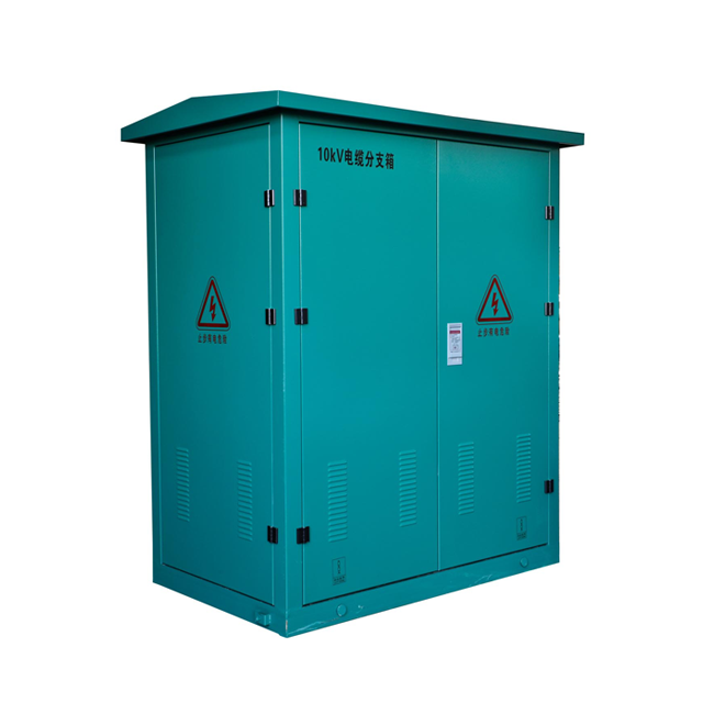
Drawout configurations are engineered for maximum serviceability and continuous operation. The core of this design is the cassette or cradle mechanism. This mechanical housing allows breakers to be physically racked in and out of the energized bus using a specialized hand crank or remote racking tool. The breakers interface with the main bus via primary disconnects (stabs) and connect to control circuits via secondary disconnect clusters.
These systems predominantly utilize Low Voltage Power Circuit Breakers (LVPCBs). LVPCBs are heavily robust devices engineered for high mechanical endurance, frequent operation, and seamless integration with drawout cassettes. They feature maintainable contacts and arc chutes, unlike sealed MCCBs. The drawout mechanism features three standard mechanical positions. In the "Connected" position, both primary power and secondary control circuits are engaged. In the "Test" position, the primary power bus is disconnected and isolated by physical shutters, but the control circuits remain active, allowing technicians to test relay logic and breaker operation safely. In the "Disconnected" or "Withdrawn" position, the breaker is fully isolated and can be extracted from the cabinet.
When specifying these systems, engineers frequently encounter standard configurations like the GCK drawout switchgear cabinet and the GCS drawout switchgear cabinet. GCK cabinets are typically deployed for motor control centers and main power distribution, offering high modularity and straightforward integration of motor starters and feeders. GCS cabinets are known for higher technical performance, smaller module steps (allowing for higher density in a single vertical section), and superior heat dissipation, making them ideal for high-capacity industrial applications.
The process of replacing a breaker in a drawout system is vastly different from a fixed system:
The technician opens the breaker locally or remotely to interrupt the load.
A racking handle is inserted into the front escutcheon of the breaker.
The technician cranks the handle to move the breaker from the "Connected" position to the "Test" position.
Further cranking moves the breaker to the "Disconnected" position, causing the internal safety shutters to drop and cover the live busbar stabs.
The cabinet door is opened, and the breaker is pulled forward onto its extension rails.
A specialized lifting hoist is attached to the breaker to safely lower it to the ground.
A spare breaker is hoisted onto the rails and racked back into the connected position.
Maximized uptime and serviceability. A failed breaker can be racked out and replaced with a spare in minutes without dropping the main bus or disrupting adjacent circuits.
Enhanced personnel safety through strict compartmentalization and closed-door racking capabilities, which drastically mitigate arc flash exposure risks.
Simplified testing and calibration via the isolated "Test" position, enabling routine maintenance of sophisticated relays without requiring a facility-wide shutdown.
Superior fault containment. Drawout switchgear typically features Form 3 or Form 4 separation, ensuring that an internal arc fault is contained within a single compartment rather than destroying the entire lineup.
Higher initial capital expenditure. The complex LVPCBs, heavy-duty cassettes, internal shutters, and extensive compartmentalization significantly increase manufacturing costs.
Larger physical footprint. Drawout cabinets are generally deeper and wider than fixed equivalents, and they require substantial front aisle clearance for breaker extraction and the use of lifting hoists.
Mechanical complexity. The racking rails, automatic shutters, and alignment pins require dedicated preventative maintenance to ensure they do not bind or jam over time.
Evaluating fixed against drawout switchgear requires a strict analysis of how each architecture responds to operational stress, maintenance demands, and facility constraints. The mechanical differences directly impact system resilience and the physical layout of the electrical room.
Regarding fault protection and system resilience, both architectures utilize sophisticated trip units to clear overcurrents and short circuits. However, drawout systems inherently provide superior internal segregation. Standard drawout designs utilize Form 3b or Form 4b separation, meaning the busbars, functional units (breakers), and cable terminals are isolated from one another using grounded metal barriers. If a catastrophic failure occurs within one breaker compartment, the metallic barriers prevent the ionized gases and plasma from propagating to the main bus or adjacent breakers. Fixed switchgear often features lower levels of separation (Form 1 or Form 2), meaning a localized fault has a higher probability of escalating into a total system failure.
Separation Type | Description | Typical Architecture |
|---|---|---|
Form 1 | No internal separation. Busbars and functional units are in the same volume. | Basic Fixed Switchboards |
Form 2a / 2b | Busbars are separated from functional units. Terminals are not separated. | Standard Fixed Switchgear (GGD) |
Form 3a / 3b | Busbars separated from units. Units separated from each other. | Advanced Fixed / Basic Drawout |
Form 4a / 4b | Busbars, units, and cable terminals are all individually separated. | Premium Drawout Switchgear (GCK/GCS) |
Maintenance, uptime, and Mean Time to Repair (MTTR) represent the most significant divergence between the two systems. Consider a scenario where a primary feeder breaker fails. In a fixed switchgear lineup, technicians must schedule an emergency outage, de-energize the main bus, verify isolation, unbolt the heavy phase conductors, remove the failed MCCB, install the new unit, torque all connections to exact specifications, and re-energize the system. This process typically results in a minimum of 4 to 8 hours of downtime. In a drawout system, a technician can don appropriate PPE, rack the failed LVPCB out to the disconnected position, lift it out of the cassette, insert a spare breaker, and rack it back into the connected position. This hot-swap process can be completed safely in under 15 minutes, preserving facility operations.
Space constraints and facility footprint often dictate the final architectural choice. Fixed switchgear cabinets are highly compact. Because the breakers are bolted directly to the bus, the depth of the cabinet is minimized. Drawout switchgear requires significantly more volume. The cassettes add depth, and the requirement for Form 4 separation adds width to each vertical section. Furthermore, drawout switchgear demands a dedicated drawout aisle in front of the equipment. Technicians need at least 1.5 to 2 meters of clear space to fully extend the breaker on its rails and maneuver a specialized lifting truck to remove the heavy LVPCB from the cradle. If the electrical room is undersized, drawout switchgear is physically impossible to maintain.
Selecting the correct switchgear architecture requires aligning the equipment's mechanical capabilities with the facility's operational mandate. Over-specifying leads to wasted capital, while under-specifying guarantees catastrophic operational disruptions.
Fixed switchgear is the optimal choice for facilities where scheduled maintenance windows are acceptable and budget constraints are tight. Commercial office buildings, retail centers, schools, and light industrial manufacturing plants typically fall into this category. In these environments, shutting down the electrical system over a weekend for routine maintenance or breaker replacement does not result in massive financial losses. Additionally, fixed switchgear is necessary for projects with severely limited electrical room square footage, where the depth and aisle clearance required for drawout cassettes simply cannot be accommodated.
Drawout switchgear is mandatory for mission-critical facilities where continuous uptime is non-negotiable. Data centers, hospitals, wastewater treatment plants, and continuous process manufacturing facilities cannot tolerate multi-hour shutdowns. In these environments, the cost of a single hour of unplanned downtime far exceeds the initial price premium of the drawout configuration. Drawout architectures are also highly recommended for facilities that require advanced power monitoring systems and frequent relay testing, as the "Test" position allows for rigorous diagnostic work without dropping the critical load.
Sourcing and installing low voltage switchgear involves navigating complex supply chains and strict mechanical tolerances. Vetting a low voltage switchgear manufacturer is the first step. Evaluate manufacturers based on their strict adherence to IEC 61439 or ANSI/NEMA standards. Scrutinize the historical reliability of their racking mechanisms and shutter assemblies, as these are the most common points of mechanical failure in drawout systems. Ensure the manufacturer guarantees long-term availability of replacement breakers, as LVPCBs are often proprietary to the cassette design.
Navigating lead times with a low voltage switchgear supplier requires careful project management. Drawout systems inherently carry longer lead times than fixed systems. The extensive internal compartmentalization, custom busbar bending required to navigate around cassettes, and the integration of complex secondary control wiring demand significant engineering and fabrication time. Standard fixed GGD cabinets can often be sourced and assembled much faster, making them advantageous for fast-track construction schedules.
Installation and commissioning present unique risks, particularly for drawout configurations. The most critical factor during installation is precise floor leveling. A drawout switchgear lineup must sit on a perfectly level concrete pad or steel channel base. If the floor is uneven by even a few millimeters across the length of the lineup, the vertical sections will twist slightly when bolted together. This microscopic twisting binds the drawout rails and misaligns the primary stabs. If the rails bind, technicians will be unable to rack the breakers in or out smoothly, entirely negating the primary benefit of the drawout architecture. Laser leveling and precise shimming are absolute requirements during commissioning.
To finalize your procurement strategy and ensure your facility's electrical infrastructure meets operational demands, execute the following steps:
Conduct a facility risk assessment to determine the exact operational impact of a four-hour unexpected power outage.
Measure the proposed electrical room, specifically calculating the front aisle clearance required for breaker extraction and lifting equipment.
Request detailed dimensional drawings and technical specifications for both GGD and GCK/GCS configurations from your shortlisted suppliers.
Evaluate the internal separation requirements based on your facility's arc flash safety protocols and local electrical codes.
A: The main difference is the mechanical connection to the busbar. Fixed switchgear uses bolted connections, requiring a system shutdown to replace breakers. Drawout switchgear uses a racking mechanism, allowing breakers to be safely removed and replaced while the main bus remains energized, drastically reducing maintenance downtime.
A: Yes. Drawout switchgear features closed-door racking, automatic safety shutters that cover energized busbars when the breaker is removed, and higher levels of internal compartmentalization. These features significantly reduce a technician's exposure to live parts and mitigate arc flash risks during maintenance.
A: These are industry-standard cabinet designations. GGD refers to a standard fixed low voltage distribution cabinet. GCK and GCS refer to drawout switchgear cabinets, with GCS typically offering higher density, smaller module steps, and superior technical performance for complex industrial applications.
A: No. Upgrading is generally not feasible. Drawout systems require completely different internal busbar routing, specialized cassettes, and larger cabinet dimensions to accommodate the racking mechanisms and compartmentalization. Transitioning requires a complete replacement of the switchgear lineup.
A: The higher cost is driven by mechanical complexity. Drawout systems require heavy-duty Low Voltage Power Circuit Breakers, precision-engineered racking cassettes, automatic safety shutters, alignment pins, heavier busbar bracing, and extensive sheet metal for internal Form 3 or Form 4 compartmentalization.
A: Drawout switchgear requires a dedicated front aisle clearance, typically 1.5 to 2 meters. This space is mandatory to fully rack the breaker out on its rails and to maneuver specialized lifting hoists or trucks required to safely extract the heavy circuit breakers from the cabinet.


